
A UWB Constant Beam Directional Antenna

A technology of beam directional and directional antennas, applied to antennas, electrical long antennas, non-resonant long antennas, etc., can solve the problems of easy waveform changes, low gain, and large difference in pattern, etc., to achieve constant beam width and stable signal transmission , the effect of small fluctuations

Active Publication Date: 2022-05-17
36TH RES INST OF CETC
View PDF9 Cites 0 Cited by
  • Summary
  • Abstract
  • Description
  • Claims
  • Application Information

AI Technical Summary

Problems solved by technology

Although the planar helical antenna has a wide operating bandwidth (10 octaves) and a relatively constant beam width, its gain is low (up to about 5dBi), the waveform is prone to change, and the beam pointing stability is poor, which is not conducive to the improvement of receiving sensitivity and pointing accuracy. ;Constant beam horn antennas generally adopt the form of corrugated horn antennas, or horn antennas whose outer arms are elliptical, exponential and other special function curves. Although they have a high gain in the working frequency band (about 10dBi), their working bandwidth Limited, no more than 3 octaves; the Vivaldi antenna has a wide operating bandwidth (10 octaves) and a constant beamwidth. Compared with the planar helical antenna, it has higher gain (up to 7-8dBi), but the entire working frequency band The pattern difference between the inner E surface and the H surface is relatively large, and the degree of equalization of the beam is not high, which affects the interception rate and detection accuracy of the detection equipment

Method used


Image

  • A UWB Constant Beam Directional Antenna
  • A UWB Constant Beam Directional Antenna
  • A UWB Constant Beam Directional Antenna

Examples


Embodiment Construction

[0026] In order to make the object, technical solution and advantages of the present invention clearer, the implementation manner of the present invention will be further described in detail below in conjunction with the accompanying drawings.

[0027] In the description of this application, it should be noted that the terms "center", "upper", "lower", "left", "right", "vertical", "horizontal", "inner", "outer" etc. The indicated orientation or positional relationship is based on the orientation or positional relationship shown in the drawings, and is only for the convenience of describing the present application and simplifying the description, rather than indicating or implying that the referred device or element must have a specific orientation, use a specific orientation construction and operation, therefore should not be construed as limiting the application. In addition, the terms "first", "second", and "third" are used for descriptive purposes only, and should not be co...


PUM


Abstract

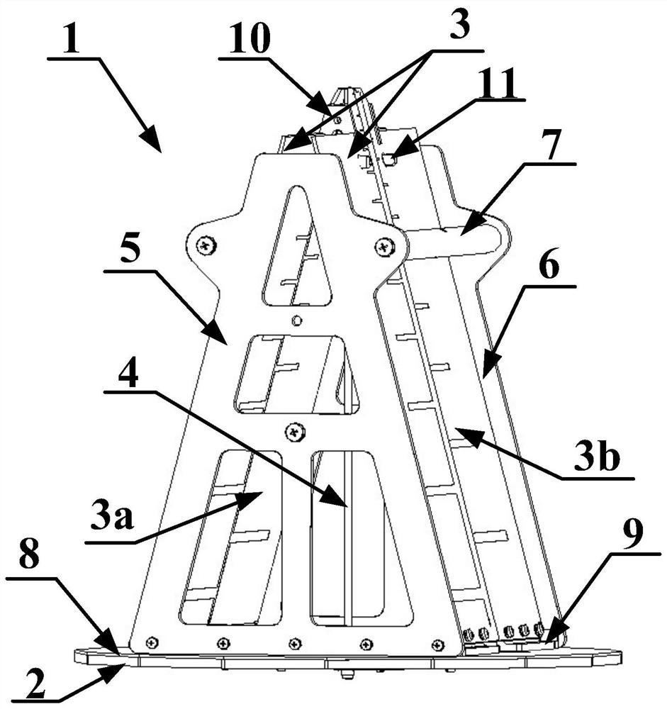
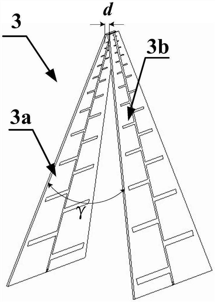
The invention discloses an ultra-wideband constant-beam directional antenna, which includes a radiator. The radiator adopts a printed logarithmic periodic antenna with non-frequency-variable ultra-wideband characteristics, including two pairs of printed logarithmic periodic antennas that are The tops of the several-period antennas close together in the direction perpendicular to the antenna plane to form an inverted V-shaped array, and at the top corners of the inverted V-shaped array, there is a preset angular distance between two pairs of printed logarithmic periodic antennas. By using a printed logarithmic periodic antenna with non-frequency variable ultra-wideband characteristics, two pairs of printed logarithmic periodic antennas are mirrored to form an inverted V-shaped array, and the two printed logarithmic periodic antennas are controlled at the top angle of the inverted V-shaped array. There is a preset vertex angle spacing at the place. With such a structural design, the beam width of the directional antenna is constant, the fluctuation is small, and the signal transmission is stable. At the same time, the radiator of this application is in the form of a printed logarithmic periodic antenna, which has a small Advantages such as simplification, light weight, easy processing, low cost and good consistency.

Description

technical field [0001] The invention relates to the technical field of antennas, in particular to an ultra-wideband constant beam directional antenna. Background technique [0002] The antenna is a mutual converter for the internal signal of the radio detection equipment to propagate between the transmission line and the free space. The performance of the antenna fundamentally determines the quality of the technical indicators of the entire detection system. Since various detection devices work in various frequency bands, an extremely wide-band electromagnetic wave space is formed in the working area. To detect multiple targets at the same time, the antennas of radar, communication and other detection devices are required to have a wide range. The pursuit of longer detection distance and higher receiving sensitivity requires greater antenna gain; the pursuit of higher interception rate and detection accuracy requires antenna beam equalization and constant beam width. In thi...

Claims


Application Information

Patent Timeline
Patent Type & Authority Patents(China)
IPC IPC(8): H01Q5/25H01Q11/10H01Q1/36H01Q1/38H01Q1/48H01Q1/50H01Q17/00
CPCH01Q5/25H01Q11/105H01Q1/36H01Q1/38H01Q1/48H01Q1/50H01Q17/00
Inventor 张建丰王庆祥
Owner 36TH RES INST OF CETC
Learn More