Method and apparatus for beamforming based on broadband antenna

a beam output and broadband technology, applied in the direction of individual energised antenna arrays, direction finders using radio waves, instruments, etc., can solve the problems of multi-path interference and signal fading, and the energy of these signals will be lost by the beam output, so as to eliminate the distortion of processed broadband signals and maintain constant width

Active Publication Date: 2006-08-17
UNILOC 2017 LLC
View PDF3 Cites 37 Cited by
  • Summary
  • Abstract
  • Description
  • Claims
  • Application Information

AI Technical Summary

Benefits of technology

[0009] It is, therefore, an object of the present invention to provide a method for beamforming based on broadband antenna In the proposed method, the effective aperture of the base antenna array is changed according to the signal frequency, so that the antenna shapes signals with different frequency into beams with constant width. On this premise, the weight vector of the antenna for different signal frequency is calculated, and then the input signals are weighted by the calculated weight vector to equalize the space gain of the antenna for each signal frequency, thus to eliminate distortion of the processed broadband signals.
[0010] Another object of the present invention is to provide a method and apparatus for beamforming with constant beam width, for use in mobile terminals with array antenna With this Rx (receiving) method and apparatus, the antenna elements can effectively reduce the odds produced when transmitting and receiving signals, thus dramatically improve the communication quality.

Problems solved by technology

Due to difference in propagation paths, the same signal may arrive at the receiver via different paths with different propagation delays and DOAs (directional angle of arrival), thus multi-path interference and signal fading are caused.
When broadband signals are received not in the direction to which the beam heads, the beam width of the antenna is relatively narrow for HF (high frequency) signals, so part of HF signals will fall to the null of the antenna pattern, thus the energy of these signals will be lost by the beam output.

Method used


Image

  • Method and apparatus for beamforming based on broadband antenna
  • Method and apparatus for beamforming based on broadband antenna
  • Method and apparatus for beamforming based on broadband antenna

Examples


Embodiment Construction

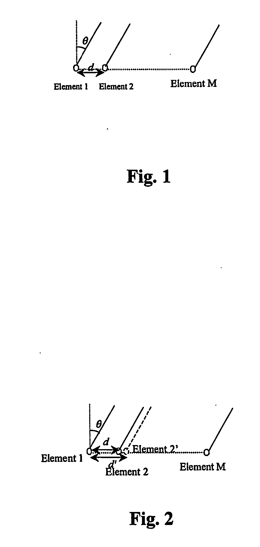
[0024] As shown in equation (1), antenna beams with different width can be acquired by changing the geometrical aperture d of the antenna; for signals with different frequency f; beams with constant width can be acquired by changing the geometrical aperture d to keep the half-power beam width θ0.5 unchanged.

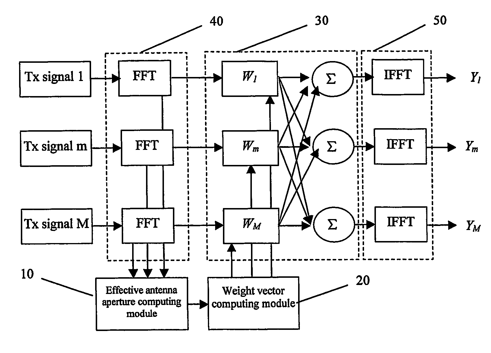
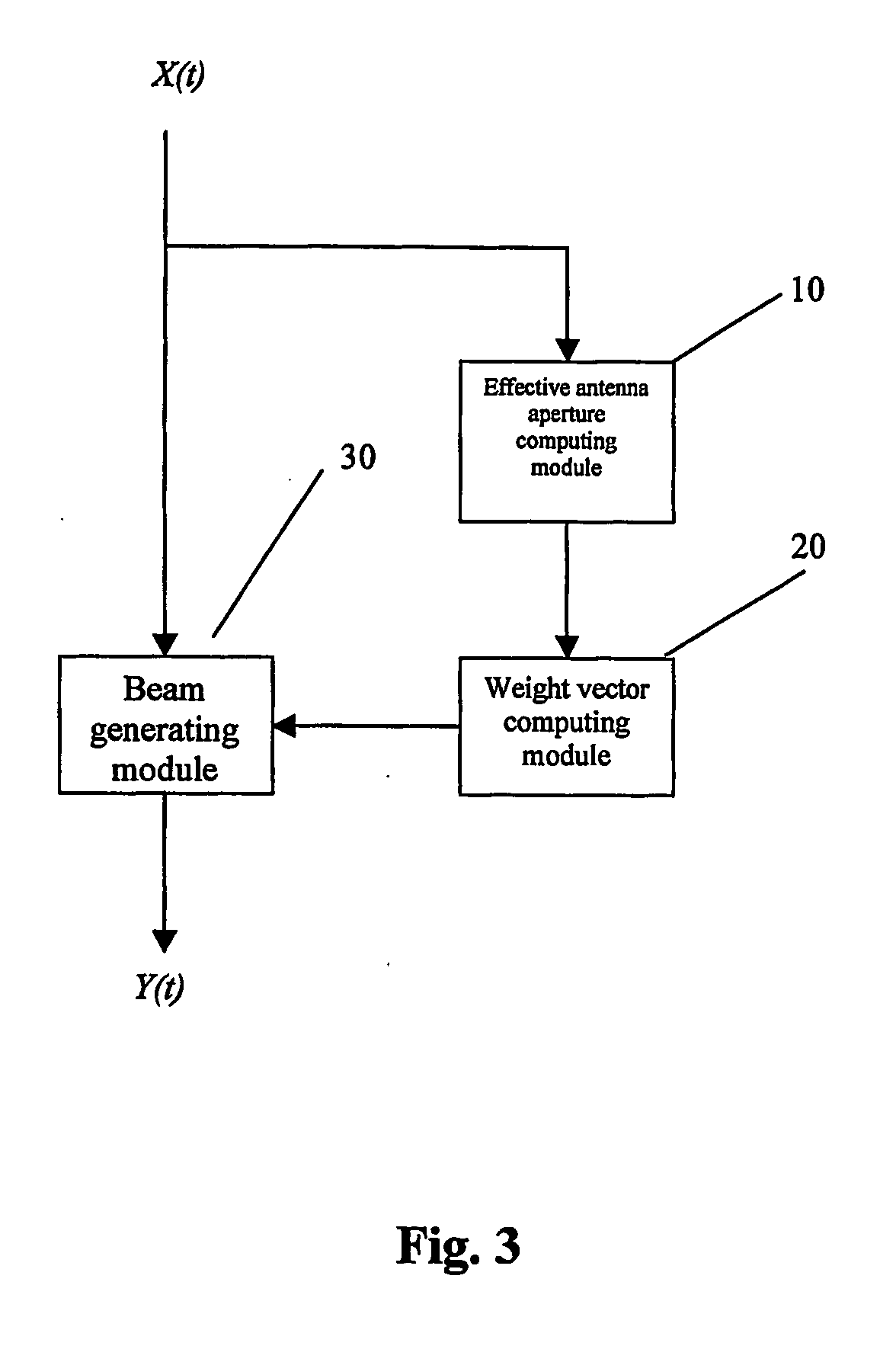
[0025] The beamforming method proposed in the present invention is based on the above-mentioned principle. The antenna can shape beams with constant width for different signal frequency, by changing the effective aperture for different signal frequency. On this premise, the weight vector of the antenna array for different signal frequency is calculated, and then input signals are weighted with the calculated weight vector so that the space gain of the antenna for each signal frequency can be equalized.

[0026] In the following, a detailed description will be given to the procedure for beamforming method, by taking the continuous antenna array as an example.

[0027] First, when the...


PUM


Abstract

A beamforming method based on broadband antenna is provided, comprising: detecting the frequency of input signals of an antenna; determining the effective antenna aperture between elements of the antenna array according to the detected frequency; computing the weight vector of each element of the antenna array to the signals according to the determined effective antenna aperture and the transmission function of the antenna array; multiplying the input signals with said weight vector of each element of the antenna array to the signals, combining them and outputting the beam signals. By performing weighting operation respectively to the input signals after a series of delaying operation, and then combining them, the single digital signals can be acquired. This effectively reduces the odds produced by the antenna between transmitting signals and receiving signals, and thus dramatically improves the communication quality.

Description

FIELD OF THE INVENTION [0001] The present invention relates generally to a beamforming method based on broadband antenna, and more particularly, to a beamforming method implemented in time domain or in frequency domain based on broadband antenna. BACKGROUND ART OF THE INVENTION [0002] In common mobile communication environment, signals communicated between the base station and the mobile terminal are transmitted along several paths between the receiver and the transmitter. Due to difference in propagation paths, the same signal may arrive at the receiver via different paths with different propagation delays and DOAs (directional angle of arrival), thus multi-path interference and signal fading are caused. [0003] By taking full advantage of the space property of signals, array antenna techniques can reduce multi-path interference and signal deterioration effectively, improve system capacity and QoS markedly, and thus won wide applications in real life. [0004] For the array antenna, b...

Claims


Application Information

Patent Timeline
Patent Type & Authority Applications(United States)
IPC IPC(8): H01Q3/00G01S3/16H04M1/00H01Q3/22H01Q3/26H01Q21/08H01Q21/22
CPCH01Q3/22H01Q21/22H01Q21/08H01Q3/26
Inventor DAI, YANZHONG
Owner UNILOC 2017 LLC
Why Eureka
Try Eureka