Woodsword handle slotting machine

A slotting machine and handle technology, applied in slotting machines, mortising machines, forming/shaping machines, etc., to prevent flying everywhere

Active Publication Date: 2020-10-16
邱锦芳
View PDF6 Cites 5 Cited by
  • Summary
  • Abstract
  • Description
  • Claims
  • Application Information

AI Technical Summary

Problems solved by technology

[0004] In order to overcome the shortcomings of manually pressing the hole opener repeatedly and intermittently moving the wooden sword handle in the slotting method of the wooden sword handle currently used, the technical problem is to provide an automatic pressing of the hole opener. Wooden sword handle moves intermittently, reducing manual operation of wooden sword handle slotting machine

Method used


Image

  • Woodsword handle slotting machine
  • Woodsword handle slotting machine
  • Woodsword handle slotting machine

Examples


Embodiment 1

[0049] A slotting machine for wooden sword handles, such as figure 1 As shown, it includes a leg 1, a bottom plate 2, a rotating placement mechanism 3, a slotting mechanism 4, and an intermittent pressing mechanism 5. A bottom plate 2 is provided on the top of the outrigger 1, and a rotating placement mechanism 3 is provided on the front side of the middle of the bottom plate 2. The bottom plate 2 The slotting mechanism 4 is installed on the right side, and the bottom plate 2 rear portion is provided with an intermittent pressing mechanism 5. Squeeze fit.

[0050]When the wooden sword handle needs to be slotted, the wooden sword handle is manually placed on the parts of the rotating placement mechanism 3, and then the parts of the intermittent pressing mechanism 5 are started, and the parts of the intermittent pressing mechanism 5 rotate counterclockwise thereupon, and the intermittent pressing mechanism 5 During the downward rotation, the left side of the parts of the interm...

Embodiment 2

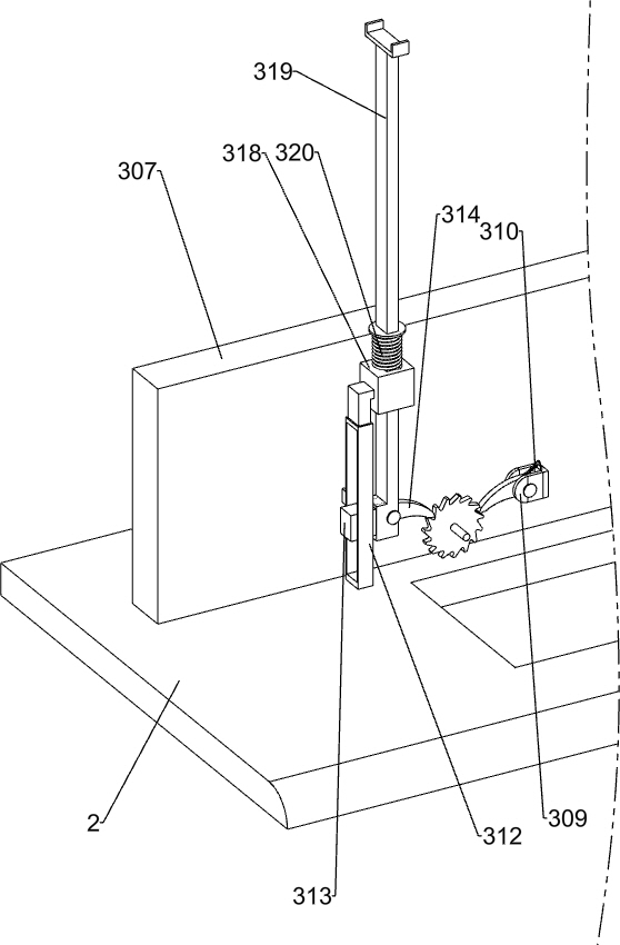
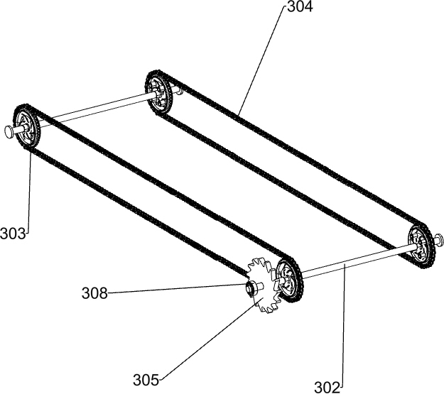
[0052] Specifically, such as Figure 2-9 and Figure 14 As shown, the rotating placement mechanism 3 includes a fixed plate 301, a rotating rod 302, a sprocket 303, a chain 304, a ratchet 305, a transmission belt 306, a riser 307, a bearing 308, a mounting block 309, a first spring 310, and a second slide rail 312, the second slider 313, the pawl 314, the limit block 315, the second spring 316, the sliding sleeve 318, the slide bar 319 and the third spring 320, the front side of the base plate 2 is rectangular and is provided with a fixed disk 301, which is located on the same Between the fixed discs 301 on the side, a rotating rod 302 is installed in a rotating manner, and the front and rear sides of the rotating rod 302 are provided with sprockets 303, between the two sprockets 303 on the rear side and the two sprockets 303 on the front side. A chain 304 is wound around, a ratchet 305 is connected to the rear of the left rotating rod 302, a bearing 308 is provided at the re...

Embodiment 3

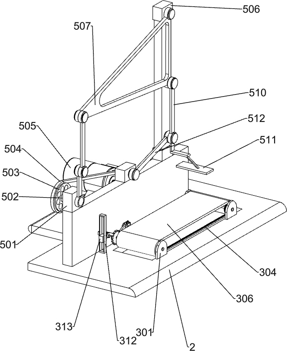
[0057] refer to Figure 10-13 As shown, the intermittent pressing mechanism 5 includes a square block 501, a round bar 502, a pulley 503, a flat belt 504, a motor 505, a vertical bar 506, a triangular pressing plate 507, a first fork 508, a second fork 509, and a third fork. 510, square pressing plate 511 and the 4th fork 512, vertical plate 307 top left side is provided with square block 501, and square block 501 middle part is rotatably equipped with round rod 502, bottom plate 2 rear side middle part is installed with motor 505, the output of motor 505 Pulleys 503 are arranged on the shaft and the rear side of the round rod 502, and a flat belt 504 is connected between the two pulleys 503. A vertical rod 506 is arranged on the right side of the top of the vertical plate 307, and a triangular pressing plate 507 is arranged on the front side of the vertical rod 506 in a swinging manner. A first swing rod 508 is installed on the front side of the round rod 502, and the upper e...


PUM


Abstract

The invention relates to a slotting machine, in particular to a woodsword handle slotting machine. The invention aims to solve the technical problem so as to provide the woodsword handle slotting machine capable of automatically pressing a hole opener, enabling a woodsword handle to move intermittently and reducing the manual operation. The invention provides the technical scheme that the woodsword handle slotting machine comprises support legs and a slotting mechanism, wherein a bottom plate is arranged on the top parts of the support legs; a rotary placement mechanism is arranged on the front side of the middle part of the bottom plate; the slotting mechanism is arranged on the side part of the bottom plate; an intermittent pressing mechanism is arranged on the rear part of the bottom plate; a part of the intermittent pressing mechanism contacts a part of the rotary placement mechanism; and the part of the intermittent pressing mechanism is matched with a part of the slotting mechanism. According to the woodsword handle slotting machine provided by the invention, through the rotary placement mechanism, the woodsword handle can be moved intermittently without the need of being directly moved by manpower; the woodsword handle can be slotted through the slotting mechanism; and through the intermittent pressing mechanism, the hole opener is automatically moved downwards intermittently without the need of being pressed by manpower.

Description

technical field [0001] The invention relates to a slotting machine, in particular to a slotting machine for wooden sword handles. Background technique [0002] In order to better combine wooden swords, slots are usually made on the wooden sword handle. When slotting, the worker places the wooden sword handle under the hole opener, and then the worker presses down on the hole opener, and the hole opener moves down to touch the wood. The sword handle is slotted, and then the worker moves the hole opener upwards and the wooden sword handle to the right. When the slot required for the wooden sword handle is directly below the hole opener, the worker stops moving the wooden sword handle and starts again. The hole opener is pressed down, and the hole opener slots the handle of the wooden sword again, and the worker repeats the above operations continuously to complete the slotting work of the wooden sword handle. [0003] The slotting method of the above-mentioned wooden sword ha...

Claims


Application Information

Patent Timeline
Patent Type & Authority Applications(China)
IPC IPC(8): B27C5/02B27C5/06B27F5/02B27G3/00
CPCB27C5/02B27C5/06B27G3/00B27F5/02
Inventor 邱锦芳
Owner 邱锦芳
Why Eureka
Try Eureka