Shifting injection mold and use method thereof

A mold and moving mold technology, which is applied in the field of displacement and injection molds, can solve the problems of plastic body falling off the side wall, the cost of shoe soles, and low production efficiency, and achieve the goals of reducing labor costs, excellent social value, and improving quality. Effect

Inactive Publication Date: 2020-10-16
李周仔
View PDF0 Cites 0 Cited by
  • Summary
  • Abstract
  • Description
  • Claims
  • Application Information

AI Technical Summary

Problems solved by technology

[0003] The existing slipper mold can only produce one part of the sole at a time, and then assemble it manually, which not only takes time and effort, but also leads to an increase in the cost of the sole, and there is a gap between the sole and the plastic body around the side wall after assembly. With the increase of use time, the plastic body around the side wall is easy to fall off from the periphery of the sole;
[0004] After the injection molding of the existing slippers mold is completed, one mold is used to produce the plastic body of the side wall on one machine, and then it is moved to another machine and put into another mold to contain injection products. This production method has many disadvantages. Due to the time difference and deformation during the handling process, it often results in a high rate of defective products and low production efficiency

Method used


Image

  • Shifting injection mold and use method thereof
  • Shifting injection mold and use method thereof

Examples


Embodiment 1

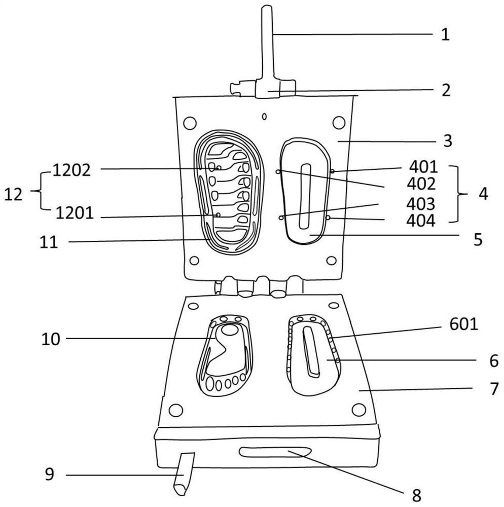
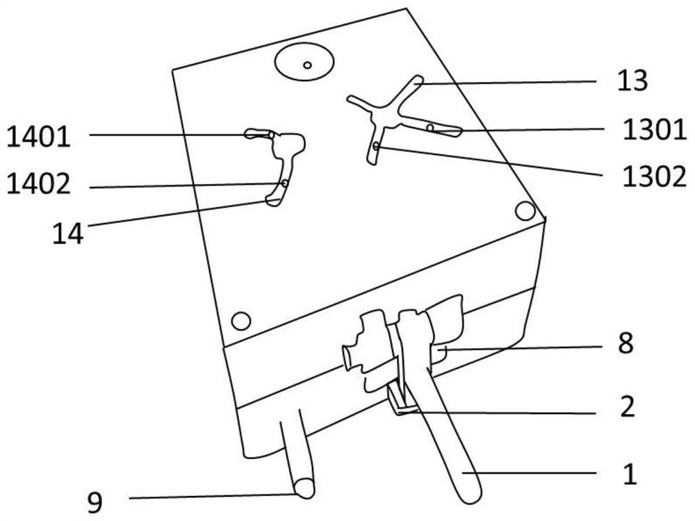
[0058] A displacement containing injection mold is provided, including: a first handle 1, a movable mold 3, and a fixed mold 7; the first handle 1 is arranged at the front end of the movable mold 3; a limiting groove 2 is also provided on the first handle 1; the The movable mold 3 and the fixed mold 7 are flexibly connected by a shaft; the inner surface of the movable mold 3 is provided with a side wall punch 5 and a shoe sole punch 11; the surrounding of the side wall punch 5 is provided with a side wall feed port 4 ; The inside of the sole punch 11 is provided with a sole feed port 12 ; the inner surface of the fixed mold 7 is provided with a side wall die 6 and a sole die 10 .

[0059] The side wall feed port 4 includes a first side wall feed port 401, a second side wall feed port 402, a third side wall feed port 403, and a fourth side wall feed port 404;

[0060] The sole feeding port 12 includes a first shoe sole feeding port 1201 and a second shoe sole feeding port 1202 ...

Embodiment 2

[0073] A displacement containing injection mold is provided, including: a first handle 1, a movable mold 3, and a fixed mold 7; the first handle 1 is arranged at the front end of the movable mold 3; a limiting groove 2 is also provided on the first handle 1; the The movable mold 3 and the fixed mold 7 are flexibly connected by a shaft; the inner surface of the movable mold 3 is provided with a side wall punch 5 and a shoe sole punch 11; the surrounding of the side wall punch 5 is provided with a side wall feed port 4 ; The inside of the sole punch 11 is provided with a sole feed port 12 ; the inner surface of the fixed mold 7 is provided with a side wall die 6 and a sole die 10 .

[0074] The side wall feed port 4 includes a first side wall feed port 401, a second side wall feed port 402, a third side wall feed port 403, and a fourth side wall feed port 404;

[0075] The sole feeding port 12 includes a first shoe sole feeding port 1201 and a second shoe sole feeding port 1202 ...


PUM


Abstract

The invention provides a shifting injection mold, characterized by at least comprising: a first handle 1, a movable mold 3, and a fixed mold 7. The first handle 1 is disposed at the front end of the movable mold 3; a limiting groove 2 is also provided on the first handle 1; the movable 3 is movably connected to the fixed mold 7 by a shaft; a side wall convex mold 5 and a sole convex mold 11 are provided on the inner surface of the movable mold 3; side wall feed ports 4 are provided around the side wall convex mold 5; a sole feed port 12 is provided in the sole convex mold 11; and a side wall concave mold 6 and a sole concave mold 10 are provided on the inner surface of the fixed mold 7.

Description

technical field [0001] The invention relates to the technical field of moulds, in particular to a shifting injection mould, and a method for using the same. Background technique [0002] Shoe molds usually refer to the molds used in the production of sports shoes, slippers, rubber shoes and other footwear. The sole is the most fundamental part required for the preparation of any shoe. In the existing production process of shoe soles, different molds are required. The plastic body around the side wall and the sole are produced, and then bonded by bonding. Therefore, the existing slipper mold still has certain defects, such as: [0003] The existing slipper mold can only produce one part of the sole at a time, and then assemble it manually, which not only takes time and effort, but also leads to an increase in the cost of the sole, and there is a gap between the sole and the plastic body around the side wall after assembly. With the increase of use time, the plastic body arou...

Claims


Application Information

Patent Timeline
Patent Type & Authority Applications(China)
IPC IPC(8): B29C33/26B29C33/42B29C33/00B29L31/50
CPCB29C33/0022B29C33/26B29C33/42B29L2031/50
Inventor 李周仔
Owner 李周仔
Why Eureka
Try Eureka