Rotary type multi-specification medicine box stamping device
A multi-specification, rotary technology, applied in stamping, printing and other directions, can solve the problems of different positions, unsuitable batch stamping, time-consuming and laborious manual stamping, etc., to achieve easy moving, labor saving, and clear stamping. Effect
- Summary
- Abstract
- Description
- Claims
- Application Information
AI Technical Summary
Problems solved by technology
Method used
Image
Examples
Embodiment 1
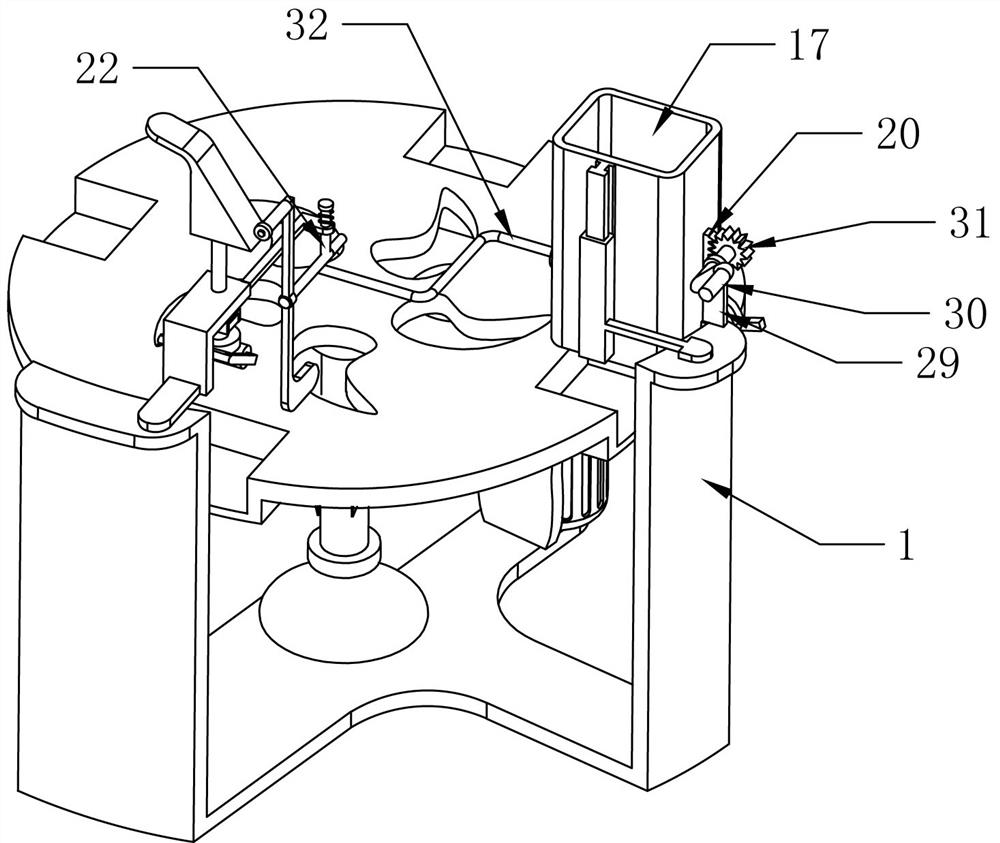
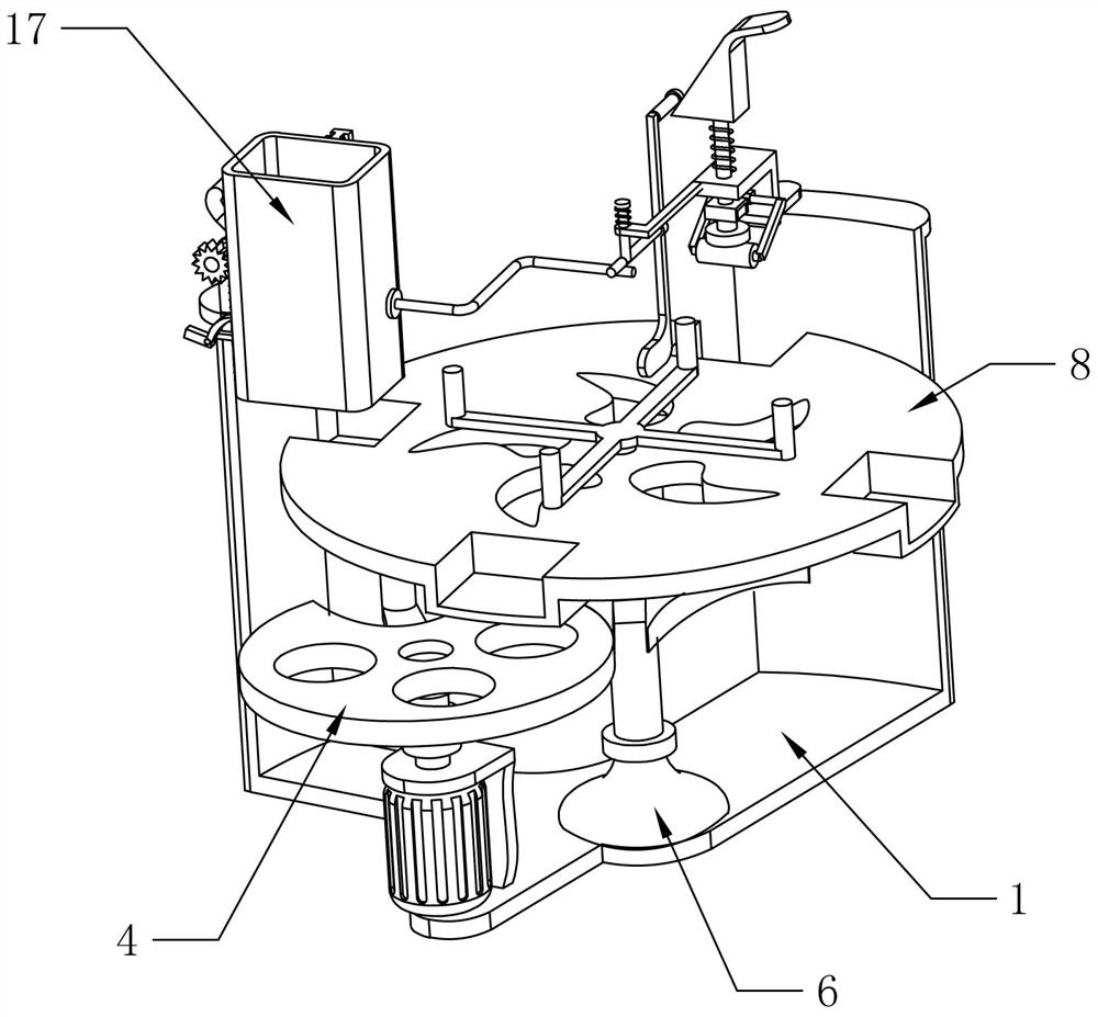
[0062] A rotary multi-standard medicine box sealing device, such as figure 1 As shown, it includes a frame 1, a turntable mechanism, a stamping mechanism and a blanking mechanism. The frame 1 is provided with two integrated right-angle L-shaped, respectively L1 and L2. The turntable mechanism is arranged at the bottom of the frame 1, and the stamp The mechanism is arranged on the frame 1, located at the top of the L1 type, and used for stamping the medicine box, and the unloading mechanism is arranged on the frame 1, located at the top of the L2, and used for installing the medicine box.
[0063] During use, the medicine box is put into the blanking mechanism, and the medicine box falls from the blanking mechanism onto the turntable mechanism. When the turntable mechanism rotates the medicine box to the bottom of the stamping mechanism, the stamping mechanism is used to seal the medicine box.
Embodiment 2
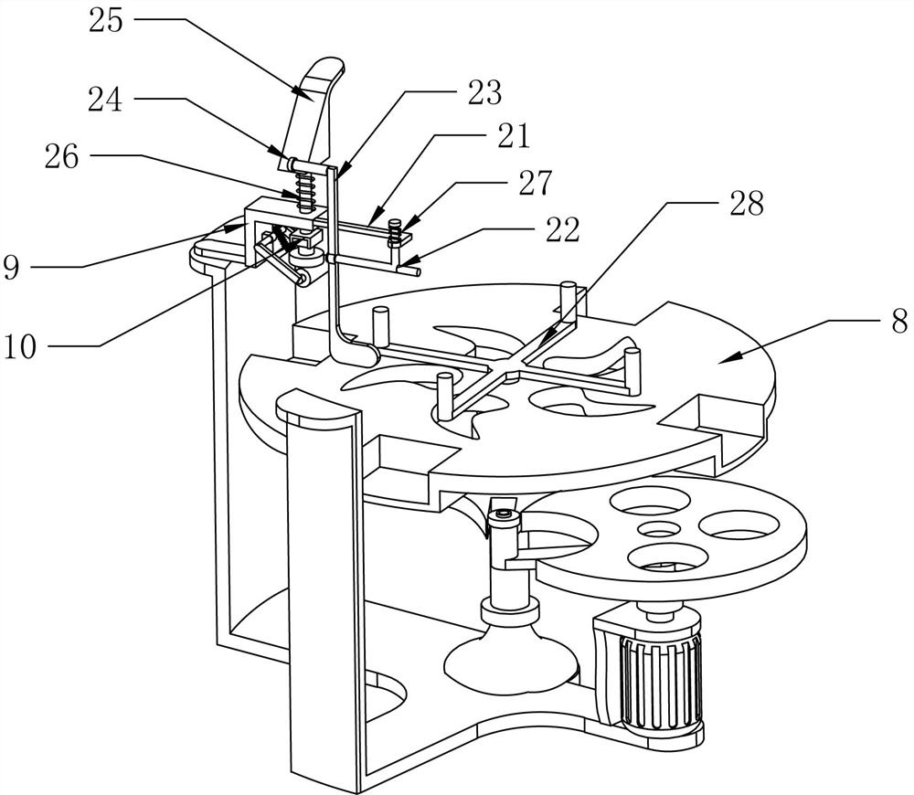
[0065] On the basis of Example 1, such as Figure 1-3 As shown, the turntable mechanism includes a motor base 2, a servo motor 3, a runner 4, a rocker 5, a rotating base 6 and an intermittent wheel 7, the motor base 2 is fixed on the front side of the bottom of the frame 1, and the servo motor 3 is installed on the motor In the seat 2, the runner 4 is installed on the output shaft of the servo motor 3 through a coupling, the runner 4 is provided with a groove, the rocker 5 is L-shaped, and one end of the rocker 5 is fixed under the groove of the runner 4, The rotating base 6 is fixed on the middle part of the frame 1, the rotating base 6 is divided into a bearing seat and a rotating shaft, and the rotating shaft can rotate in the bearing seat, the intermittent wheel 7 is fixedly connected with the rotating shaft on the rotating seat 6, and the intermittent wheel 7 and the rotating wheel 4 are matched in the On the same horizontal plane, four slots are arranged on the outer edg...
Embodiment 3
[0072] On the basis of Example 2, such as Figure 4-5 Shown, also include fixed frame 21, slide bar 22, swing bar 23, roller 24, inclined block 25, nickel-plated spring 26, strong spring 27 and push rotating rod 28, fixed frame 21 one end is fixed on connecting plate 9 in parallel, The other end is provided with a vertical through hole, and the sliding rod 22 is T-shaped. The top of the T-shaped sliding rod 22 passes through the through hole of the fixed frame 21, and is connected up and down. The swing rod 23 is Z-shaped, and the middle part and the rear end of the sliding rod 22 rotate Connection, the roller 24 is fixed on the upper end of the swing rod 23, the inclined block 25 is fixed on the top of the slide bar 10, the inclined block 25 is in contact with the roller 24, the nickel-plated spring 26 is set on the slide bar 10, and one end of the nickel-plated spring 26 is fixed on the connection Plate 9, the other end of the nickel-plated spring 26 is connected to the incl...
PUM
 Abstract
Description
Claims
Application Information
 - R&D
- Intellectual Property
- Life Sciences
- Materials
- Tech Scout
- Unparalleled Data Quality
- Higher Quality Content
- 60% Fewer Hallucinations
Browse by: Latest US Patents, China's latest patents, Technical Efficacy Thesaurus, Application Domain, Technology Topic, Popular Technical Reports.
© 2025 PatSnap. All rights reserved.Legal|Privacy policy|Modern Slavery Act Transparency Statement|Sitemap|About US| Contact US: help@patsnap.com


