Pipeline mounting device
A pipeline installation and storage technology, applied in transportation and packaging, multi-axis trolleys, trolley accessories, etc., can solve the problems of cumbersome pipeline calibration, impact on pipeline installation efficiency, labor intensity of workers, etc., to improve efficiency, simplify calibration, reduce The effect of work intensity
- Summary
- Abstract
- Description
- Claims
- Application Information
AI Technical Summary
Problems solved by technology
Method used
Image

Examples
Embodiment Construction
[0034] In order to make the object, technical solution and advantages of the present invention clearer, the present invention will be further described in detail below in conjunction with the accompanying drawings and embodiments. It should be understood that the specific embodiments described here are only used to explain the present invention, not to limit the present invention.
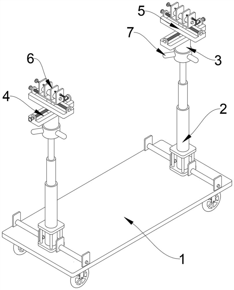
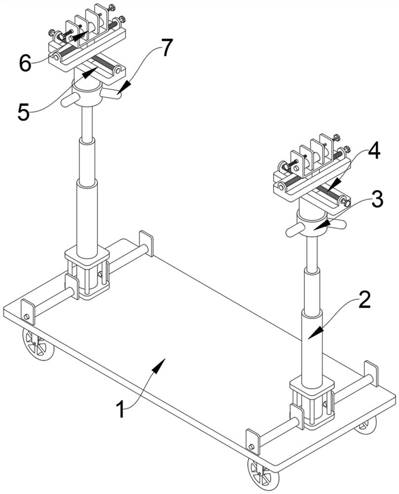
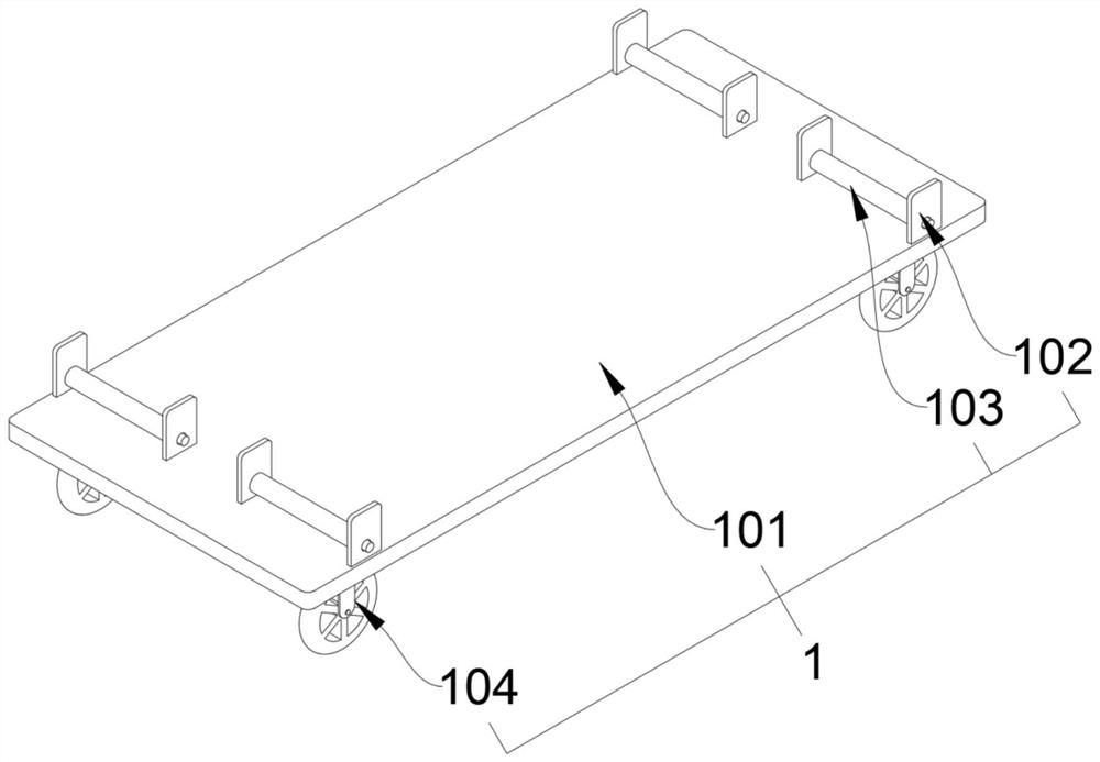
[0035] refer to Figure 1-7 , a pipeline installation device, including a transport mechanism 1, the upper end of the transport mechanism 1 is screwed with two hydraulic rods 2, the transport mechanism 1 includes a vehicle body load-bearing plate 101, four first support plates 102, four first rollers 103 and Four rolling pulleys 104, the upper end of the vehicle body bearing plate 101 and the two sides of the two hydraulic rods 2 are welded with the first support plate 102, and the middle positions of the four first support plates 102 are all rotatably connected with the first roller 103, the vehic...
PUM
 Abstract
Description
Claims
Application Information