Annular tool and method for deformation straightening of highly permeable sand layer large-diameter shield tail shield

A technology with a large diameter and shield tail, which is applied in the testing of machine/structural components, measuring devices, shaft equipment, etc. It can solve problems such as the escape of the shield machine, the inability of the shield machine to continue to excavate, and the plastic deformation of the tail shield. The effect of ensuring construction safety

Pending Publication Date: 2020-10-16
CCCC SECOND HARBOR ENG
View PDF0 Cites 2 Cited by
  • Summary
  • Abstract
  • Description
  • Claims
  • Application Information

AI Technical Summary

Problems solved by technology

When the passive earth pressure on the part of the tail shield is greater than the strength of its own steel plate, the tail shield will produce plastic deformation, resulting in the contact and extrusion of the tail shield steel plate, the propulsion cylinder shoe and the segment, and the shield machine will be trapped and cannot continue to excavate
When encountering this kind of shield tunneling problem, it is necessary to use the correction device to correct the deformation of the tail shield, so that the shield machine can get out of trouble and continue to tunnel

Method used


Image

  • Annular tool and method for deformation straightening of highly permeable sand layer large-diameter shield tail shield
  • Annular tool and method for deformation straightening of highly permeable sand layer large-diameter shield tail shield
  • Annular tool and method for deformation straightening of highly permeable sand layer large-diameter shield tail shield

Examples


Embodiment 1

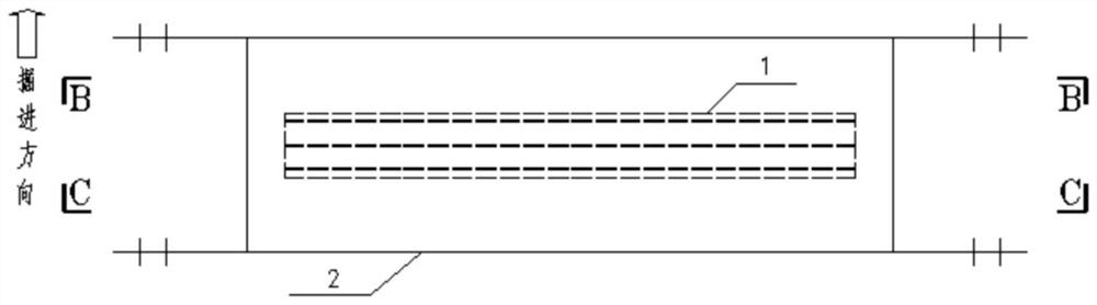
[0070] A circular tooling 1 for correcting the deformation of the tail shield of a large-diameter shield in a strong water-permeable sand layer, including:

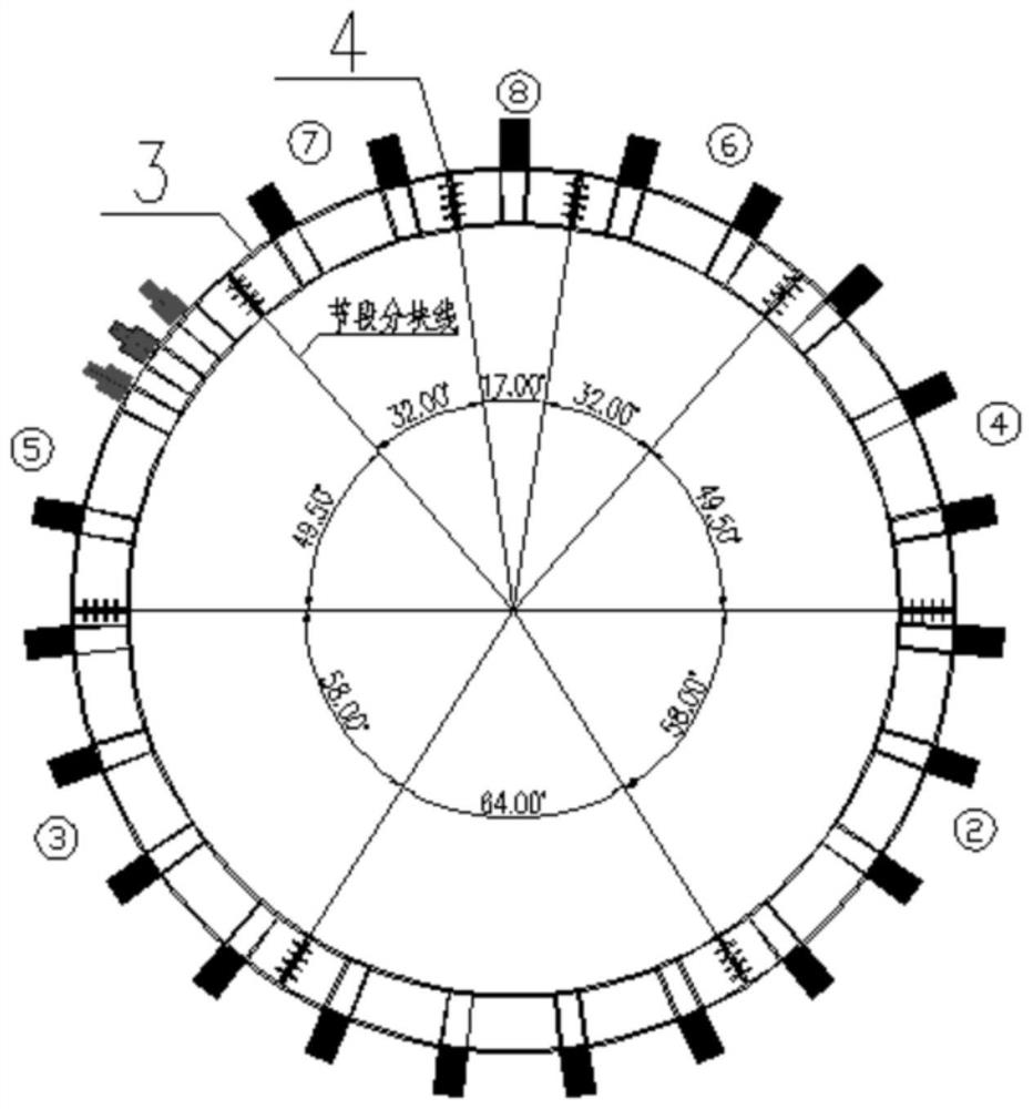
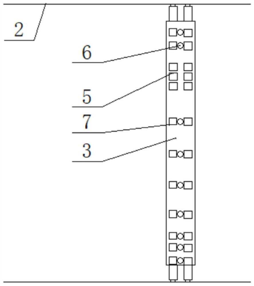
[0071] Reaction force support frame 3, which is a ring-shaped structure, the outer arc surface of the reaction force support frame 3 is provided with first pier 7 along the longitudinal and circumferential intervals, the first pier located in the longitudinal direction of reaction force support frame 3 7 is provided with a pre-tightening jack 6, and a number of correction jacks 5 are provided in the tail shield deformation area 16 corresponding to the outer arc surface of the reaction force support frame 3. There is no backing plate here, and the area of ​​the cylinder of the jack is used as the pushing correction surface. If the effect is not good, consider increasing the top iron or curved steel plate to change the pushing correction area to increase the effect.

[0072] Backing plate 8, which fills the gap between the ...


PUM


Abstract

The invention discloses an annular tool and method for deformation straightening of a highly permeable sand layer large-diameter shield tail shield. The annular tool comprises a counterforce support frame, a base plate and a meniscus structure. The counterforce support frame is of an annular structure. The outer cambered surface of the counterforce support frame is provided with first buttresses at intervals in the longitudinal and circumferential directions. A pre-tightening jack is arranged between the first buttresses located in the longitudinal direction of the counterforce support frame.A plurality of straightening jacks are arranged in a tail shield deformation area corresponding to the outer cambered surface of the counterforce support frame. A gap between the first buttresses andthe tail shield is filled with the base plate. The meniscus structure is installed on the inner cambered surface, corresponding to the tail shield deformation area, of the counterforce support frame.Through the annular tool and method, the problems of tail shield deformation and tail shield rounding straightening of a shield tunneling machine are solved.

Description

technical field [0001] The invention relates to the field of shield tunnel construction. More specifically, the present invention relates to a ring-shaped frock and a method for correcting the deformation of the tail shield of a large-diameter shield in a strong water-permeable sand layer. Background technique [0002] Shield construction has become an important part of tunnel construction, and more and more shield machines have been put into tunnel construction. With the increase of shield tunneling projects, there are more and more problems with tunnel tunneling machines in different strata. When the shield machine excavates in the water-rich and dense sand layer, the stratum is dense, and a large foundation reaction force and passive earth pressure will be generated during the deflection correction process of the shield machine. When the partial passive earth pressure on the tail shield is greater than the strength of its own steel plate, the tail shield will produce pl...

Claims


Application Information

Patent Timeline
Patent Type & Authority Applications(China)
IPC IPC(8): E21D9/06E21D11/08G01B21/20G01B21/32G01L5/00G01M13/00
CPCE21D9/06E21D9/0607E21D11/08G01B21/20G01B21/32G01L5/0061G01M13/00
Inventor 翟世鸿何源韩晓明钟涵杨睿贺创波杨擎朱金彭张飞雷陈培帅许超朱宏欣
Owner CCCC SECOND HARBOR ENG
Why Eureka
Try Eureka