Piezoelectric driving type resonance air pump

A technology of piezoelectric drive and piezoelectric vibrator, applied in the direction of variable capacity pump components, pumps, pump components, etc., can solve the problem of poor gas output effect, limited deformation ability of diaphragm piezoelectric vibrator, and reduced working effect of the pump body and other problems, to achieve the effect of easy maintenance, small size and improved service life

Active Publication Date: 2020-10-16
CHANGCHUN UNIV
View PDF5 Cites 1 Cited by
  • Summary
  • Abstract
  • Description
  • Claims
  • Application Information

AI Technical Summary

Problems solved by technology

The diaphragm piezoelectric vibrator has limited deformation ability, and the output effect on gas is very poor. At higher frequencies, the working effect of the entire pump body is greatly reduced.

Method used


Image

  • Piezoelectric driving type resonance air pump
  • Piezoelectric driving type resonance air pump
  • Piezoelectric driving type resonance air pump

Examples


Embodiment 1

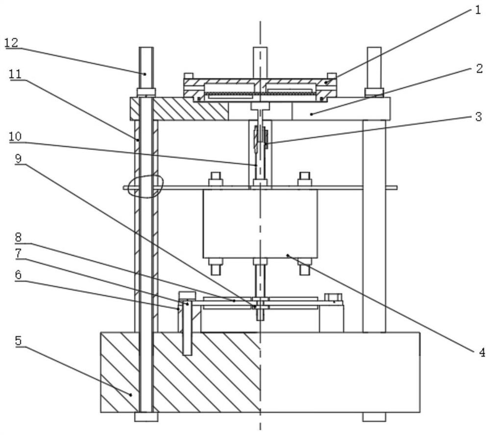
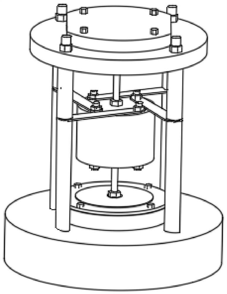
[0022] See Figure 1-5 , a piezoelectric-driven resonant air pump, including a cavity 1, a lower cavity 2 and a base 5, the base 5 is a cylindrical structure, the top of the base 5 is fixedly connected to a positioning ring 6, and the positioning ring 6 is a circular ring Shaped structure, the top of the positioning ring 6 is provided with a piezoelectric vibrator 8, the piezoelectric vibrator 8 is installed on the positioning ring 6 through a number of fastening bolts, and the top of the base 5 is evenly provided with a number of columns 11, the column 11 is a circular tubular structure, and the tops of all the columns 11 are provided with a lower cavity 2, and the lower cavity 2 is installed on the column 11 through a stud 12, and the lower cavity 2 is a circular plate structure, and the lower cavity 2 is mounted on the column 11 through a stud 12. The axis of the cavity 2 coincides with the axis of the positioning ring 6, and the top of the lower cavity 2 is provided with a...

Embodiment 2

[0025]The difference from Embodiment 1 is that the mass mechanism 4 includes a mass block 404, which is sleeved on the outside of the resonance rod 10, and the outside of the resonance rod 10 is provided with a matching mass block 404. The first nut washer 402, the top of the mass block 404 is provided with a number of spring pieces 401 in a circular array, one end of the spring piece 401 is set on the stud 12, and the other end of the spring piece 401 is installed by a mounting bolt On the mass block 404, the second nut washer 403 matched with the spring sheet 401 is sleeved on the mounting bolt, and all the spring sheets 401 are distributed in a spiral structure. By setting the spiral spring sheet 401, it can Greatly reducing the stiffness of the entire device is beneficial to reducing the natural frequency of the entire device, and can further improve the working stability of the entire device.

[0026] The working principle of Embodiment 1-2: Vibration is generated by the ...


PUM


Abstract

The invention discloses a piezoelectric driving type resonance air pump. The piezoelectric driving type resonance air pump comprises a cavity body, a lower cavity body and a base, a positioning ring is fixedly connected to the top end of the base, a piezoelectric vibrator is arranged at the top end of the positioning ring and installed on the positioning ring through a plurality of fastening bolts, a plurality of stand columns are evenly arranged at the top end of the base, the top ends of all the stand columns are jointly provided with the lower cavity body, the lower cavity is installed on the stand columns through studs, the top end of the lower cavity is provided with a clamping groove, the cavity body is installed in the clamping groove; and the bottom end of a resonance rod penetrates through the piezoelectric vibrator and is sleeved with a nut, and the resonance rod is sleeved with a mass mechanism. According to the piezoelectric driving type resonance air pump, the resonance frequency of the piezoelectric driving type resonance air pump is changed by arranging the mass mechanism, low-frequency work below 400 HZ can be achieved, the piezoelectric driving type resonance air pump can further work under the high-frequency work condition above 400 HZ, the whole piezoelectric driving type resonance air pump is simple in overall structure and small in size, magnetic interference is not generated at all, magnetic interference is not received, and compared with a traditional air pump, the piezoelectric driving type resonance air pump is more suitable for working in complex environments.

Description

technical field [0001] The invention relates to the technical field of air diaphragm pumps, in particular to a piezoelectric driven resonant air pump. Background technique [0002] The air diaphragm pump is a new type of conveying machinery, which uses compressed air as the power source. It can pump all kinds of corrosive liquids, liquids with particles, high viscosity, volatile, flammable, and highly toxic liquids. . [0003] In the two symmetrical working chambers of the pump, each is equipped with an elastic diaphragm to form two independent chambers. The intermediate shaft integrates the two diaphragms into one body. The air distribution valve controls the pressurization of each chamber. After the air enters the gas distribution valve, it pushes one side of the diaphragm, driving the two diaphragms connected by the link to move synchronously. At the same time, the gas in the other working chamber is discharged from the pump and reaches the end of the stroke, and the ga...

Claims


Application Information

Patent Timeline
Patent Type & Authority Applications(China)
IPC IPC(8): F04B45/047F04B39/00F04B39/14
CPCF04B45/047F04B39/00F04B39/14
Inventor 田晓超李庆华赵昌龙贺春山于淼候跃谦赵剑李志瑶杨凤双
Owner CHANGCHUN UNIV
Why Eureka
Try Eureka