High-strength drain pipe
A drainage pipe and high-strength technology, applied in the field of drainage pipes, can solve problems such as the rupture of the plastic ribs of the pipe body, the influence of the strength of the pipe body, and the weakening of the compressive capacity, so as to reduce the probability of rupture, ensure the support strength, and ensure The effect of stress resistance
- Summary
- Abstract
- Description
- Claims
- Application Information
AI Technical Summary
Problems solved by technology
Method used
Image

Examples
Embodiment 1
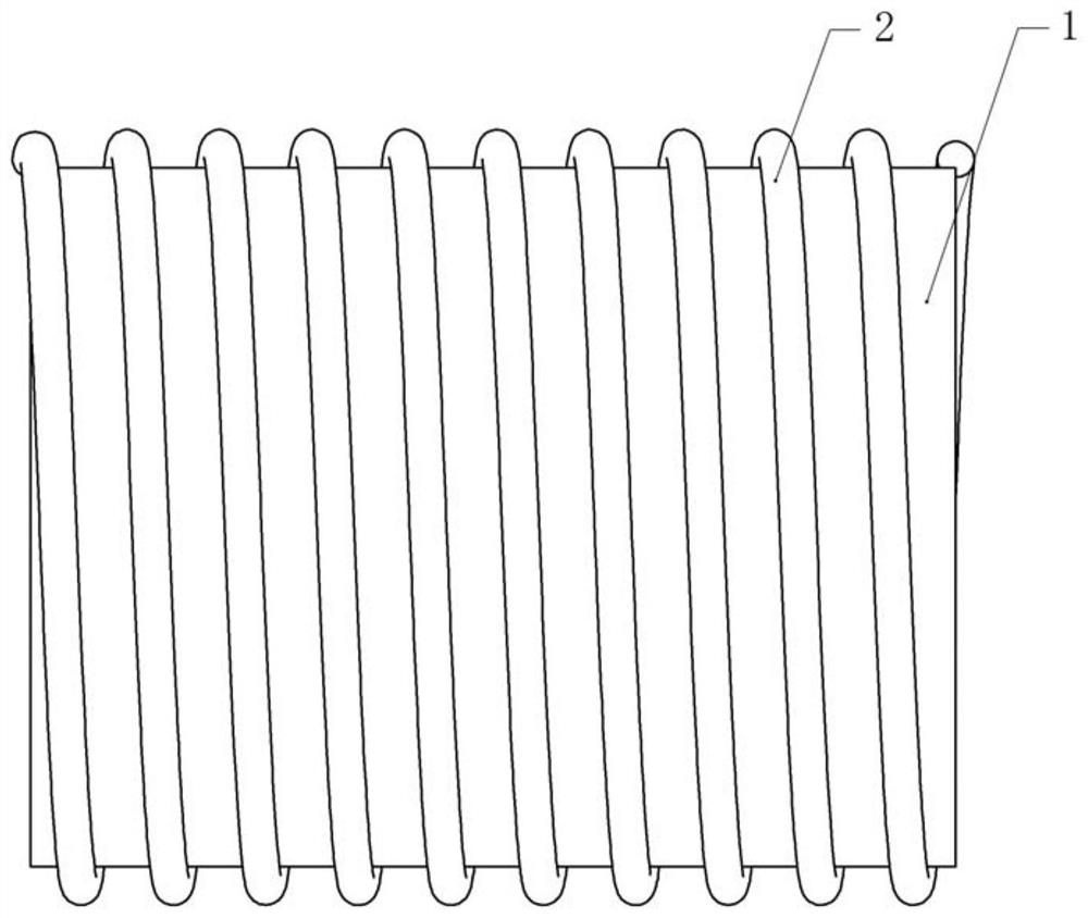
[0028] Basic as attached figure 1 And attached figure 2 As shown, a high-strength drainage pipe includes a pipe body 1, and the pipe body 1 includes an inner layer 12 and an outer layer 11. In this embodiment, the inner layer 12 is thermally compounded on the inner wall of the outer layer 11, and the inner layer 12 is composed of a fiber mesh. , and between the fiber net and the inner wall of the outer layer 11, a corrosion-resistant layer (not shown) is coated, and the corrosion-resistant layer is made of a corrosion-resistant paint, such as: Teflon paint, and the outer layer 11 is made of PE material.
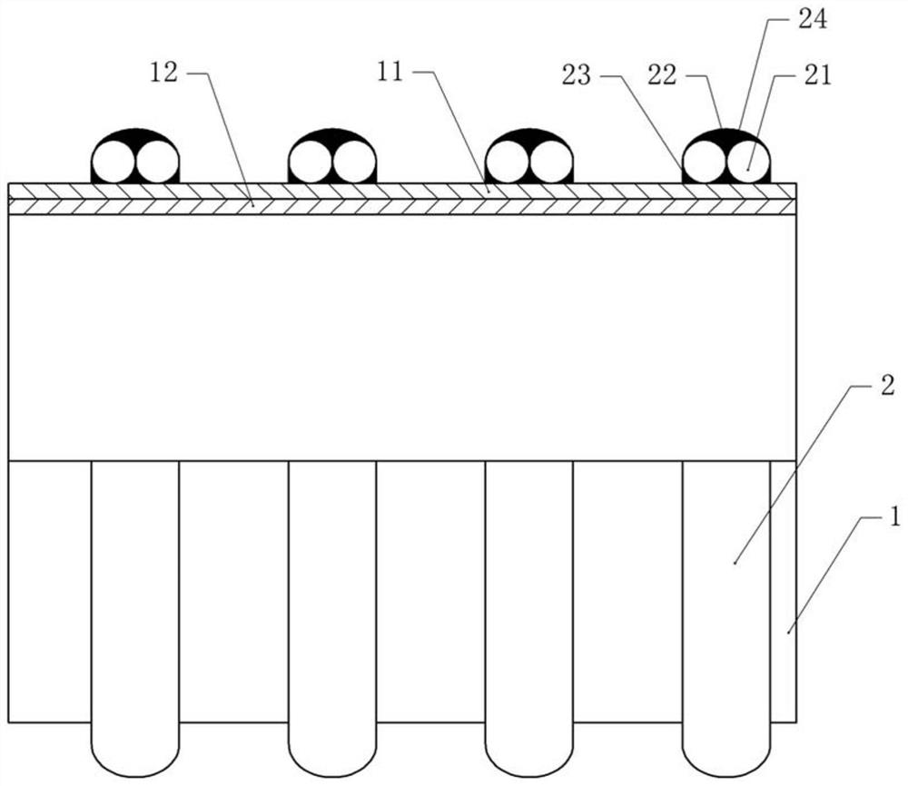
[0029] A spirally arranged outer tube 2 is thermally compounded on the tube body 1. The outer tube 2 is made of PE material. A number of movable support tubes 21 are installed inside the outer tube 2, that is, there is a certain distance between the support tube 21 and the outer tube 2. As for the gap, there are two support tubes 21 in this embodiment, and the space between...
Embodiment 2
[0031] The difference between embodiment two and embodiment one is that, as attached figure 1 And attached figure 2 As shown, a movable filling layer 22 is filled between the outer tube 2 and the support tube 21, and the filling layer 22 is made of granular PE material. The specific installation method is as follows: the outer tube 2 is thermally compounded on the outer wall of the outer layer 11, the side wall of the outer tube 2 thermally compounded with the outer wall of the outer layer 11 is the inner wall 23 of the outer tube, and the side wall of the outer tube 2 away from the outer layer 11 is the outer wall. Tube outer wall 24 . The support pipe 21 is extended into the outer pipe 2, and the support pipe 21 is arranged along the helical direction of the outer pipe 2, and then the granular PE material is filled into the space between the outer pipe 2 and the support pipe 21 to form a filling layer 22 . The filling layer 22 composed of granular PE material filled into...
Embodiment 3
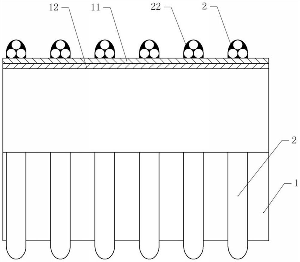
[0037] The difference between the third embodiment and the first embodiment is that, as attached image 3 As shown, three support tubes 21 are installed inside the outer tube 2, and the three support tubes 21 form a triangular structure. The specific installation method is as follows: first insert two support tubes 21 close to the inner wall of the outer tube 2 close to the tube body 1, then insert a support tube 21 on the upper part of the other two support tubes 21, and then fill the outer tube 2 Granular PE material, the granular PE material constitutes the filling layer 22 .
[0038]In this embodiment, the three support tubes 21 forming a triangle support the outer tube 2 , the compression resistance of the outer tube 2 is enhanced, and the probability of deformation or rupture of the outer tube 2 is reduced when being hit. As a result, the probability of rupture of the outer tube 2 is reduced, and the compressive strength of the tube body 1 is improved. Compared with Em...
PUM
 Abstract
Description
Claims
Application Information
 - R&D
- Intellectual Property
- Life Sciences
- Materials
- Tech Scout
- Unparalleled Data Quality
- Higher Quality Content
- 60% Fewer Hallucinations
Browse by: Latest US Patents, China's latest patents, Technical Efficacy Thesaurus, Application Domain, Technology Topic, Popular Technical Reports.
© 2025 PatSnap. All rights reserved.Legal|Privacy policy|Modern Slavery Act Transparency Statement|Sitemap|About US| Contact US: help@patsnap.com