
Cloth airing device for textile processing

A drying device and cloth technology, applied in the field of textile processing, can solve problems such as surface pollution of cloth, and achieve the effects of improving the distribution range, improving the reflectivity, and improving the drying efficiency.

Inactive Publication Date: 2020-10-16
李立志
View PDF1 Cites 2 Cited by
  • Summary
  • Abstract
  • Description
  • Claims
  • Application Information

AI Technical Summary

Problems solved by technology

A drying rack for textiles in the above-mentioned patent has the following disadvantages: when the existing device is used to dry the cloth, it may cause one end of the cloth to hang down on the ground due to the relatively long size of the cloth, which may cause damage to the cloth. Contamination of the surface of the cloth

Method used


Image

  • Cloth airing device for textile processing
  • Cloth airing device for textile processing
  • Cloth airing device for textile processing

Examples


Embodiment 1

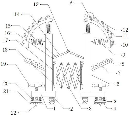
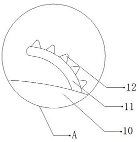
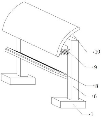
[0029] refer to Figure 1-3 , a cloth drying device for textile processing, comprising two drying rods 6, a lifting mechanism 3 connected by bolts between the outer walls of the opposite side of the two drying rods 6, and the lifting mechanism 3 consists of two fixing frames 17 and a plurality of Composed of connecting rods, and a rotational connection is formed between two adjacent connecting rods. One side outer wall of the two fixing frames 17 is provided with a fixing port 18, and the fixing port 18 forms a sliding connection with the connecting rods. The two drying rods 6 The outer wall of the first spring 9 is connected with a first spring 9 by bolts, and one side of the outer wall of the first spring 9 is connected with a drying board 10 by bolts. The bolts are connected with a plurality of barbs 11, and one side of the outer wall of the barbs 11 is provided with a plurality of tooth blocks 12, and the shape of the barbs 11 is arc.

[0030] Wherein, a hinge 16 is conne...

Embodiment 2

[0038] refer to Figure 4 , a cloth drying device for textile processing. Compared with Embodiment 1, the two ends of the outer walls on one side of the two drying rods 6 are connected with damping bearings 23 by bolts, and the outer walls on one side of the damping bearings 23 are rotationally connected. Sleeve 24 is arranged, and the inwall of sleeve 24 is plugged with sleeve rod 26, and one side outer wall of sleeve 24 is provided with threaded opening, and the inwall of threaded opening is threadedly connected with limit bolt 25, can jack-up the top of cloth, so that The utility model is used for drying the bottom of the cloth, which improves the drying efficiency of the device for the cloth.

[0039] Working principle: when in use, the device is moved to a suitable position through the moving wheel 2. After the movement is completed, the distance between the two drying rods 6 is adjusted through the lifting mechanism 3. After the adjustment is completed, the handle 19 is ...


PUM


Abstract

The invention discloses a cloth airing device for textile processing. The cloth airing device for textile processing comprises two airing rods, a lifting mechanism is fixedly connected between the outer walls of the opposite sides of the two airing rods, the lifting mechanism is composed of two fixing frames and a plurality of connecting rods, every two adjacent connecting rods are rotationally connected, fixing openings are formed in the outer walls of one sides of the two fixing frames, the fixing openings are in sliding connection with the connecting rods, first springs are fixedly connected to the outer walls of the two airing rods, airing plates are fixedly connected to the outer walls of one sides of the first springs, the two airing plates are each in an arc shape, and a plurality of barbs are fixedly connected to the outer walls of one sides of the two airing plates. According to the cloth airing device, one end of cloth can be prevented from falling on the ground to pollute the surface of the cloth, the cloth can be prevented from sliding down from the device due to the gravity of the cloth, the airing efficiency of the device on the cloth can be conveniently improved, andthe surface of a prism can be cleaned.

Description

technical field [0001] The invention relates to the technical field of textile processing, in particular to a cloth drying device for textile processing. Background technique [0002] During textile processing, it is necessary to dry the cloth through a drying device. [0003] After retrieval, the Chinese patent authorization number is CN107604611B, which discloses a drying rack for textiles, including a drying board. The four corners of the bottom of the drying board are fixedly connected with a first bracket, and the bottom of the opposite side of the first bracket is Both of them are fixedly connected with a sliding rod, and the number of the sliding rods is two. The surface of the sliding rod is covered with two sliding sleeves, and the bottom of the sliding sleeve is fixedly connected with a second bracket. The present invention is provided with a drying board, a first support, a sleeve, a sliding sleeve, a sliding rod, a second support rod, a movable shaft, a third su...

Claims


Application Information

Patent Timeline
Patent Type & Authority Applications(China)
IPC IPC(8): F26B9/10F26B25/02F26B25/18F24S23/70
CPCF26B9/10F26B25/02F26B25/18F24S23/70F24S2023/87Y02E10/40
Inventor 李立志
Owner 李立志
Learn More