Eureka AIR delivers breakthrough ideas for toughest innovation challenges, trusted by R&D personnel around the world.

Push-pull type electromagnet projectile launcher

A projectile launcher and push-pull technology, which is applied to electromagnetic launchers, weapon types, weapons without explosives, etc., can solve the problems of poor user experience and competitiveness, unsatisfactory user experience, and inconvenient operation, etc. Variety of playing methods, stable power and good effect

Pending Publication Date: 2020-10-16
巴根那
View PDF0 Cites 2 Cited by
  • Summary
  • Abstract
  • Description
  • Claims
  • Application Information

AI Technical Summary

Problems solved by technology

[0002] Existing projectile launchers mainly fall into three categories: manual, pneumatic and electric. The technologies of the three are relatively mature and popular, but each has its own advantages and disadvantages. Among them, manual launchers need to be loaded and fed manually every time they launch a projectile. It can directly feed bombs or simulate bullet shells, but it is inconvenient to operate, and the user experience and competitiveness are not good. Pneumatic launchers use alkane compressed gas as the main power source, and release compressed gas to push out projectiles. Pneumatic launchers are powered The reaction force generated by the launch is strong, that is, the recoil force. The user experience is good and it is closer to the real ammunition launcher. However, the pneumatic launcher is greatly affected by the temperature. If the temperature is too low, the power will drop significantly; the existing electric launcher The motor rotates to drive the gear, the gear drives the piston to move, and then the spring quickly bounces back the piston, and the compressed air pushes out the projectile. The stable power output of the electric launcher is the first choice for existing sports competitions. While the real ammo launcher is similar, its experience is not ideal

Method used


Image

  • Push-pull type electromagnet projectile launcher
  • Push-pull type electromagnet projectile launcher

Examples


Embodiment Construction

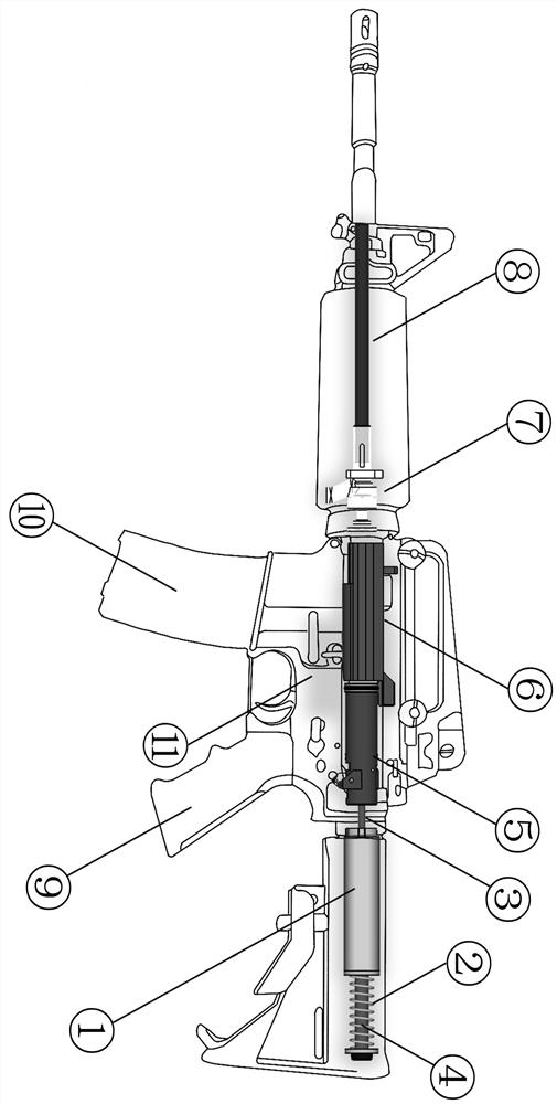
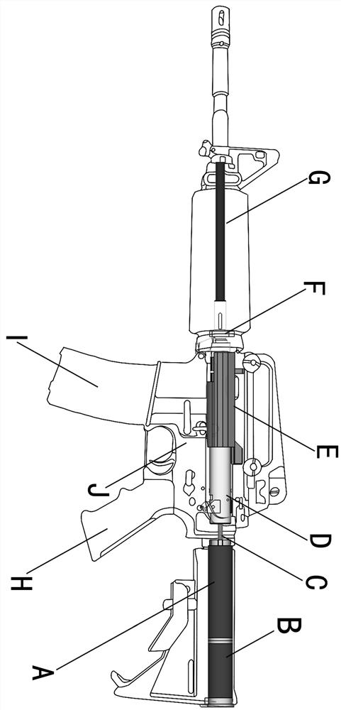
[0011] Please refer to: Figure (1) Spring Return Type Push-Pull Electromagnet Projectile Launcher, Figure (2) Push-Pull Electromagnet Reset Type Push-Pull Electromagnet Projectile Launcher.

[0012] The push-pull electromagnet projectile launcher uses 7.4V-48V power supply; after the push-pull electromagnet is energized, the moving iron core makes a linear motion, and the principle of stopping when the power is off, the moving iron core drives the piston to compress the gas in the cylinder, and the return spring Or reset the moving iron core with a push-pull electromagnet to complete a working cycle.

[0013] Figure (1) shows the spring return push-pull electromagnet projectile launcher, which is mainly composed of ① push-pull electromagnet coil, ② return spring, ③ push-pull connecting rod, ④ moving iron core, ⑤ piston, ⑥ cylinder, ⑦ push nozzle , ⑧Launcher inner tube, ⑨Grip battery compartment, ⑩Launcher magazine, ⑪Launcher main body;

[0014] Figure (2) shows the push-pull ...


PUM


Abstract

The invention discloses a push-pull type electromagnet projectile launcher. The push-pull type electromagnet projectile launcher is characterized in that the push-pull type electromagnet projectile launcher uses an electromagnetic coil, a movable iron core and a push-pull connecting rod to drive a piston to do reciprocating motion and compress gas, so that a projectile is pushed out, and the launching process is completed. According to the push-pull type electromagnet projectile launcher, when the movable iron core resets under the action of a reset spring or a push-pull electromagnet for resetting, strong recoil force is generated, the projectile supply modes are diversified, projectiles can be directly supplied, projectiles can further be supplied by a simulation cartridge case, shell throwing action is generated, more real experience can be brought to a user; as shown in the figure (1), the push-pull electromagnet (1) is electrified, so that the movable iron core (4) drives the push-pull connecting rod (3) to do push-pull motion, meanwhile, a connecting rod (3) drives the piston (5) to move in an air cylinder (6); and the push-pull type electromagnet projectile launcher is simpler in structure, better and more real in experience and more suitable for competitive events such as playing and aerobic exercise.

Description

technical field [0001] The invention belongs to the field of toys and fitness equipment, and in particular provides an electric pellet launcher equipped with a push-pull electromagnet. Background technique [0002] Existing projectile launchers mainly fall into three categories: manual, pneumatic and electric. The technologies of the three are relatively mature and popular, but each has its own advantages and disadvantages. Among them, manual launchers need to be loaded and fed manually every time they launch a projectile. It can directly feed bombs or simulate bullet shells, but it is inconvenient to operate, and the user experience and competitiveness are not good. Pneumatic launchers use alkane compressed gas as the main power source, and release compressed gas to push out projectiles. Pneumatic launchers are powered The reaction force generated by the launch is strong, that is, the recoil force. The user experience is good and it is closer to the real ammunition launcher...

Claims


Application Information

Patent Timeline
Patent Type & Authority Applications(China)
IPC IPC(8): F41B6/00
CPCF41B6/003
Inventor 巴根那
Owner 巴根那
Why Eureka
Eureka Blog
Learn More