Check patentability & draft patents in minutes with Patsnap Eureka AI!

System for automatically adjusting input delay, output delay and input and output delay

A technology that automatically adjusts and delays signals. It is applied in the direction of coupling/interface of logic circuits, electrical components, and electronic switches using field effect transistors. To overcome the offset, ensure the correct and true effect

Pending Publication Date: 2020-10-16
HERCULES MICROELECTRONICS CO LTD
View PDF0 Cites 0 Cited by
  • Summary
  • Abstract
  • Description
  • Claims
  • Application Information

AI Technical Summary

Problems solved by technology

As the speed of sending signals becomes faster and faster, the sending window of the sending end will also shift with the PVT of different process voltage parameter conditions, which will affect the accuracy and authenticity of the output signal

Method used


Image

  • System for automatically adjusting input delay, output delay and input and output delay
  • System for automatically adjusting input delay, output delay and input and output delay
  • System for automatically adjusting input delay, output delay and input and output delay

Examples


Embodiment Construction

[0029] The technical solutions of the present application will be described in further detail below with reference to the drawings and embodiments.

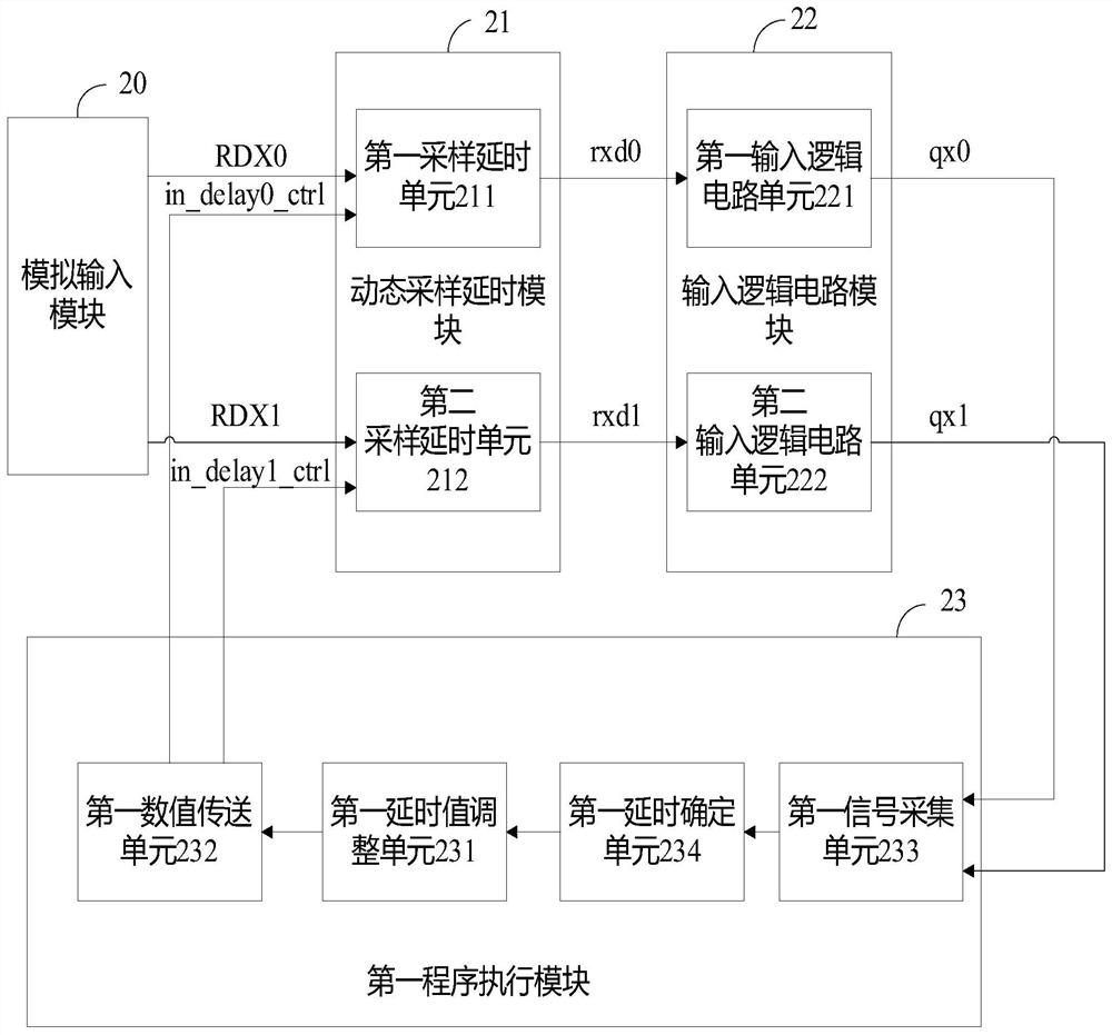
[0030] The embodiment of the present application discloses a system for automatically adjusting the input delay, and the inventive concept of the system is firstly introduced below.

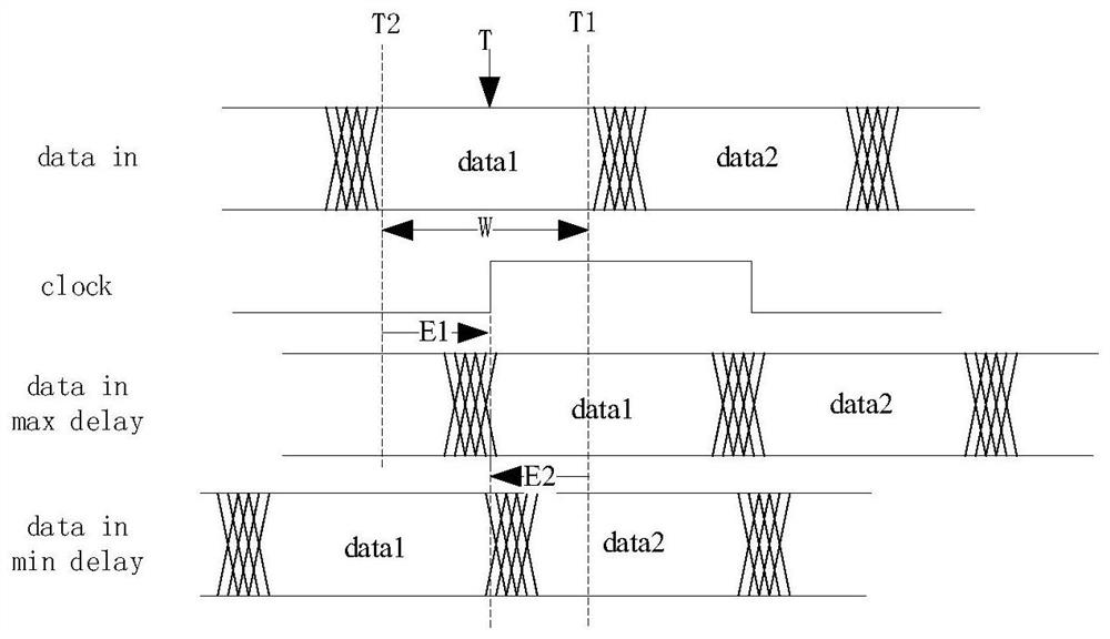
[0031] Taking the input signal as an example, figure 1 The timing relationship between the input signal (datain) and the sampling clock control signal (clock) is shown. like figure 1 As shown, the sampling window W1 is the data segment between the first boundary T1 and the second boundary T2 of the input signal (datain), and the time T is the intermediate time between the first boundary T1 and the second boundary T2 of the input signal (datain). value. When the sampling edge of the sampling clock control signal (clock) is in the middle of the sampling window W1, the sampled data has the largest noise margin, which can ensure the correctness and a...


PUM


Abstract

The embodiment of the invention relates to a system for automatically adjusting input delay, output delay and input and output delay, and the system comprises: an analog input module which is used forreceiving an input signal; a dynamic sampling delay module which is used for sampling the input signals according to the first sampling delay value and the second sampling delay value to respectivelyobtain a first sampling signal and a second sampling signal, wherein the first sampling delay value is a fixed value at the beginning, and the second sampling delay value is adjustable; an input logic circuit module which is used for performing analog-digital processing on the first sampling signal and the second sampling signal to obtain a first digital signal and a second digital signal respectively; and a first program execution module which is used for dynamically adjusting the second sampling delay value according to a comparison result by comparing the first digital signal with the second digital signal, and correcting the first sampling delay value according to multiple dynamic adjustment results, wherein the first sampling signal under the control of the corrected first sampling delay value is used as a sampling result.

Description

technical field [0001] The present application relates to the field of automatic control, in particular, to a system for automatically adjusting input delay, output delay and input-output delay. Background technique [0002] In the high-speed interface system, the interface signal is transmitted to the internal circuit by the serial port receiving end RX of the high-speed input and output (IO) module, and is sampled by the associated clock or the internal recovery clock. As the speed of interface signals becomes faster and faster, the sampling window at the receiving end will shift with the PVT of different process voltage parameter conditions, which will affect the accuracy and authenticity of sampling. Therefore, it is very important for the receiving end of the receiving system to adjust the position of the sampling window in an adaptive manner. [0003] Similarly, the sending signal is sent to the outside by the serial port TX of the high-speed input and output (IO) mod...

Claims


Application Information

Patent Timeline
IPC IPC(8): H03K17/28H03K19/0185
CPCH03K17/28H03K19/0185
Inventor 薛庆华王海力
Owner HERCULES MICROELECTRONICS CO LTD
Features
  • R&D
  • Intellectual Property
  • Life Sciences
  • Materials
  • Tech Scout
  • Unparalleled Data Quality
  • Higher Quality Content
  • 60% Fewer Hallucinations
Learn More