Camera module, electronic equipment and vehicle with same
A technology for camera modules and electronic equipment, applied to parts of color TVs, parts of TV systems, TVs, etc., can solve problems such as temperature rise, energy consumption, and high temperature, and achieve reduced thickness, lower overall height, and improved The effect of cooling capacity
- Summary
- Abstract
- Description
- Claims
- Application Information
AI Technical Summary
Problems solved by technology
Method used
Image

Examples
no. 1 example
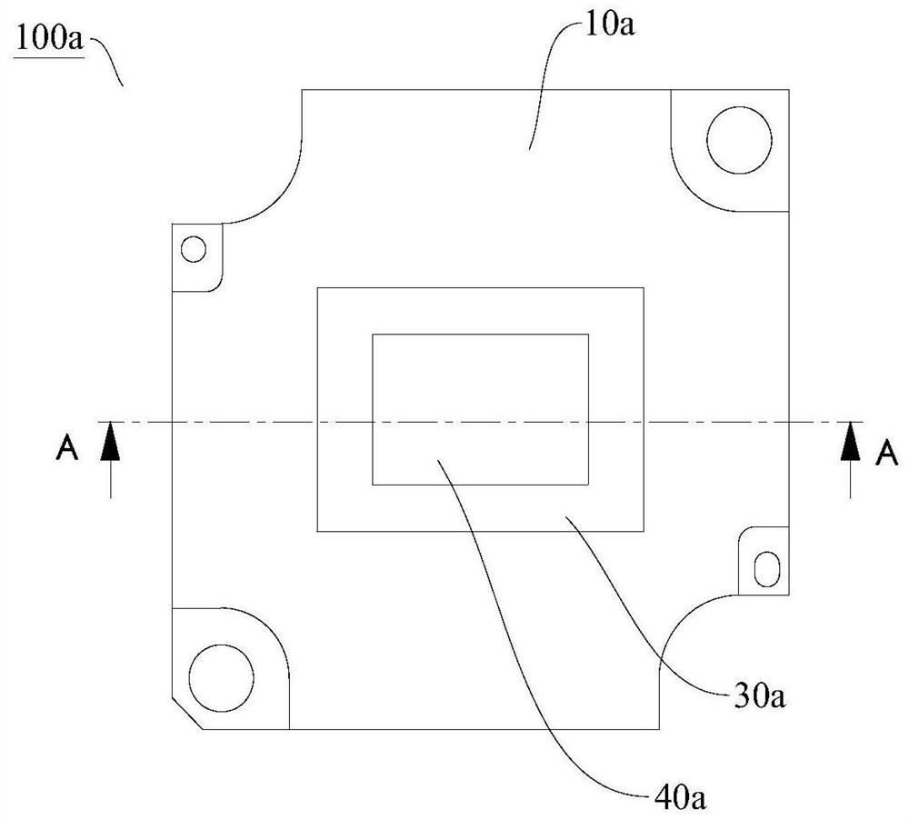
[0043] Refer below figure 1 and figure 2 The camera module 100a according to the first embodiment of the present invention will be described.
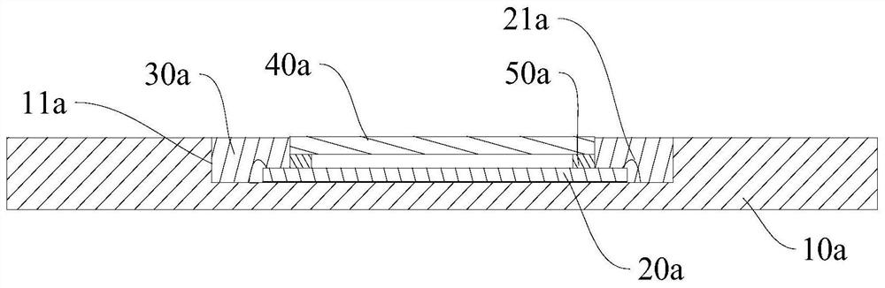
[0044] The camera module 100a according to the first embodiment of the present invention includes: a circuit board 10a, an image chip 20a, a first connecting portion 30a, and a cover plate 40a.
[0045] One side of the circuit board 10a has a receiving groove 11a. The image chip 20a is disposed in the receiving groove 11a, and the image chip 20a is electrically connected to the circuit board 10a through the electrical connection portion 21a. The first connecting portion 30a is connected between the image chip 20a and the inner wall of the receiving groove 11a, and the first connecting portion 30a covers the electrical connecting portion 21a. The cover plate 40a is arranged on the side of the image chip 20a away from the circuit board 10a, and the cover plate 40a is fixedly connected to the image chip 20a (or the cover plate 40a is ...
no. 2 example
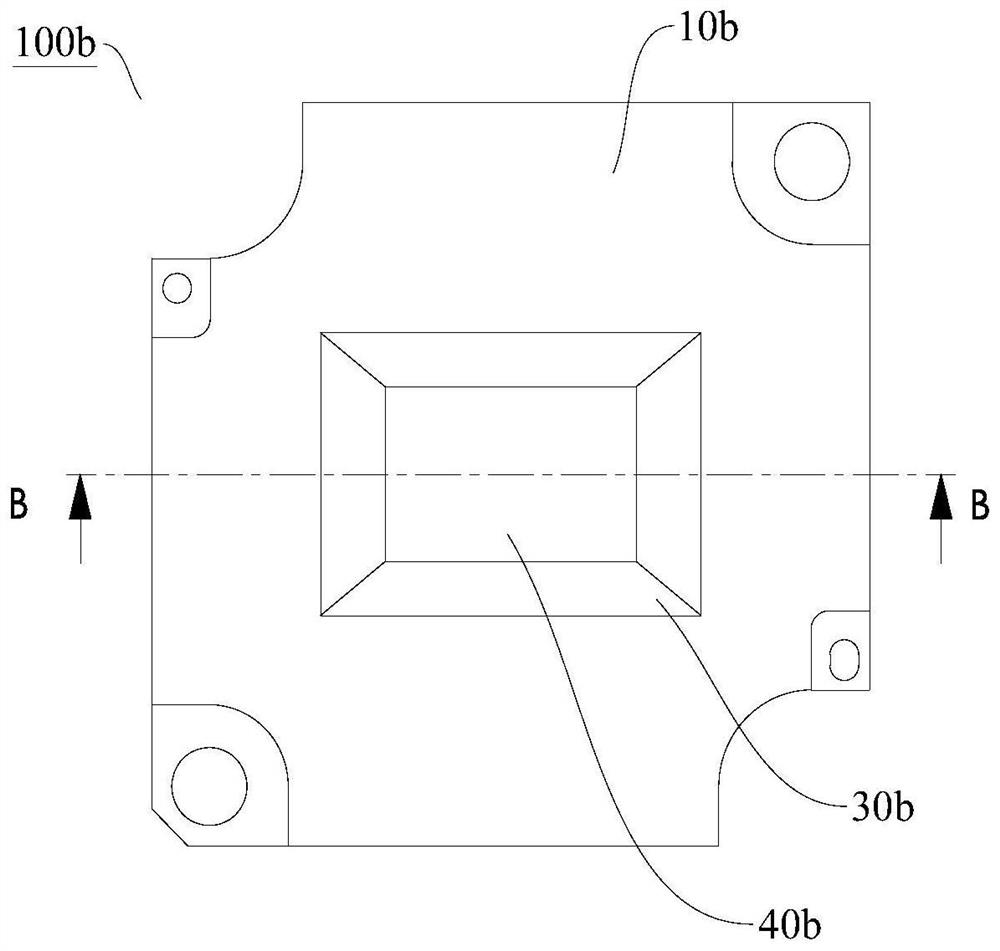
[0056] The main difference between this embodiment and the first embodiment lies in: the shape of the top surface of the first connecting portion. In the first embodiment, the shape of the top surface of the first connecting portion 30a is flush with the top surface of the circuit board. In this embodiment, the shape of the surface of the first connecting portion 30b is inclined. The above-mentioned multiple embodiments are all applicable to this application, and details are not repeated here.
[0057] The camera module 100b according to the first embodiment of the present invention includes: a circuit board 10b, an image chip 20b, a first connecting portion 30b, and a cover plate 40b.
[0058]One side of the circuit board 10b has a receiving groove 11b. The image chip 20b is disposed in the receiving groove 11b, and the image chip 20b is electrically connected to the circuit board 10b through the electrical connection portion 21b. The first connecting portion 30b is connect...
no. 3 example
[0062] The main difference between this embodiment and the first embodiment and the second embodiment is that in the first two embodiments, the cover plate 40a
[0063] (or 40b) is fixedly connected with the image chip 20a (or 20b), or the cover plate is fixed with the image chip and the circuit board. In this embodiment, the cover plate 40c is only fixed with the circuit board 20c and has no direct contact with the image chip 20c. .
[0064] Refer below Figure 5 and Figure 6 The camera module 100c according to the third embodiment of the present invention will be described in detail.
[0065] The camera module 100c according to the third embodiment of the present invention includes: a circuit board 10c, an image chip 20c, a first connecting portion 30c, and a cover plate 40c.
[0066] One side of the circuit board 10c has a receiving groove 11c. The image chip 20c is disposed in the receiving groove 11c, and the image chip 20c is electrically connected to the circuit bo...
PUM
 Abstract
Description
Claims
Application Information
 - R&D
- Intellectual Property
- Life Sciences
- Materials
- Tech Scout
- Unparalleled Data Quality
- Higher Quality Content
- 60% Fewer Hallucinations
Browse by: Latest US Patents, China's latest patents, Technical Efficacy Thesaurus, Application Domain, Technology Topic, Popular Technical Reports.
© 2025 PatSnap. All rights reserved.Legal|Privacy policy|Modern Slavery Act Transparency Statement|Sitemap|About US| Contact US: help@patsnap.com