Self-falling type efficient concrete mixer

A concrete mixer, self-falling technology, applied in cement mixing equipment, clay preparation equipment, grain processing, etc., can solve the problems of poor mixing effect and long time consumption

Inactive Publication Date: 2020-10-20
中豪建设股份有限公司
View PDF12 Cites 2 Cited by
  • Summary
  • Abstract
  • Description
  • Claims
  • Application Information

AI Technical Summary

Problems solved by technology

[0005] The purpose of the present invention is to provide a self-falling high-efficiency concrete mixer that is fast, efficient and has a good mixing effect for the above-mentioned problems of long time consumption and poor mixing effect

Method used


Image

  • Self-falling type efficient concrete mixer
  • Self-falling type efficient concrete mixer
  • Self-falling type efficient concrete mixer

Examples


Embodiment 1

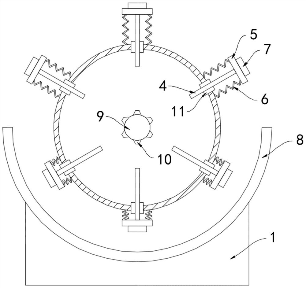
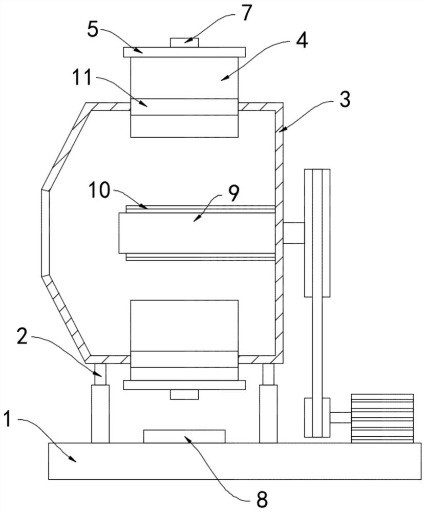
[0020] like Figure 1-2 As shown, a self-falling high-efficiency concrete mixer includes a base 1, and the upper end of the base 1 is connected to a rotating cylinder 3 through a support wheel 2. The rotating cylinder 3 is provided with a plurality of movable plates 4 arranged in the radial direction. The movable plate 4 is arranged in an annular array, the movable plate 4 runs through the side wall of the rotating cylinder 3 and is slidably connected with the rotating cylinder 3, and a sealing strip 11 is slid on the side wall of the movable plate 4, and the sealing strip 11 is fixedly connected with the rotating cylinder 3 to enhance The sealing effect between the movable plate 4 and the rotating cylinder 3 prevents the concrete from flowing out.

[0021] One end of the plurality of movable plates 4 is fixedly connected with a fixed plate 5, the side wall of the fixed plate 5 and the rotating cylinder 3 is fixed by a spring 6, and a magnet block 7 is installed on the side wa...

Embodiment 2

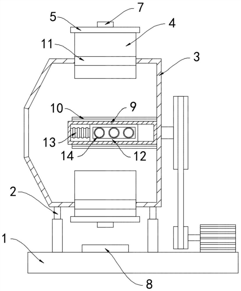
[0024] like image 3 As shown, the difference between this embodiment and Embodiment 1 is that: a thermal conduction frame 12 is slidably connected in the crushing cylinder 9, and the thermal conduction frame 12 is fixed to the end of the crushing cylinder 9 through a telescopic air bag 13, and the telescopic air bag 13 is filled with heat For expansion and contraction medium, a plurality of conductive coils 14 are fixedly connected in the heat conduction frame 12 , and the conductive coils 14 are arranged parallel to the axial direction of the crushing cylinder 9 .

[0025] In this embodiment, when the crushing cylinder 9 rotates with the rotating cylinder 3, the heat conducting frame 12 and the conductive coil 14 rotate with the crushing cylinder 9. According to the principle of electromagnetic induction, when the magnetic flux in the closed coil changes, a Inductive current, then the magnetic flux generated by the permanent magnetic strip 8 in the conductive coil 14 changes...


PUM


Abstract

The invention belongs to the field of constructional engineering machinery, and particularly relates to a self-falling type efficient concrete mixer. The self-falling type efficient concrete mixer comprises a base, the upper end of the base is rotationally connected with a rotating cylinder through a supporting wheel, a plurality of movable plates arranged in the radial direction are arranged in the rotating cylinder, and the plurality of movable plates are arranged in an annular array mode; the movable plates penetrate through the side wall of the rotating cylinder and are in sliding connection with the rotating cylinder, the ends, away from one another, of the plurality of movable plates are fixedly connected with fixed plates, the fixed plates are fixed to the side wall of the rotatingcylinder through springs, and magnet blocks are installed on the side walls, away from the movable plates, of the fixed plates; and a permanent magnet strip arranged in an arc shape is arranged on theupper surface of the base, the same poles of the permanent magnet strip and the magnet blocks repel each other, a crushing cylinder extending in the axis direction of the rotating cylinder is arranged in the rotating cylinder, and a plurality of ribs are fixedly connected to the side wall of the crushing cylinder. According to the self-falling type efficient concrete mixer, in the stirring process, concrete can fully fall off, stirring is uniform, the effect is good, and the working efficiency is greatly improved.

Description

technical field [0001] The invention belongs to the field of construction machinery, in particular to a self-falling high-efficiency concrete mixer. Background technique [0002] Concrete mixer is a machine that mixes cement, sandstone aggregate and water to make concrete mixture. When the self-falling concrete mixer is working, the mixing drum rotates around its horizontal axis, and the materials added to the mixing drum are driven by the blades. After lifting to a certain height, it falls by its own weight, and this repeated movement achieves the effect of uniform mixing. [0003] When the traditional self-falling concrete mixer mixes the concrete, the concrete needs to be repeatedly lifted up and dropped to achieve a good mixing effect, which takes a long time and is not conducive to the rapid construction of construction projects. During the long-term mixing process, the concrete is very easy to cool and solidify, which increases the difficulty of mixing. On the other h...

Claims


Application Information

Patent Timeline
Patent Type & Authority Applications(China)
IPC IPC(8): B28C5/04B28C5/46B02C19/00
CPCB02C19/005B28C5/04B28C5/466
Inventor 杨尚李玲玲
Owner 中豪建设股份有限公司
Why Eureka
Try Eureka