Automatic material-dividing switching device

A conversion device, automatic technology, applied in the direction of transportation and packaging, loading/unloading, conveyor objects, etc., can solve the problems of complex control system, residual raw material powder, and high cost

Inactive Publication Date: 2020-10-20
HUNAN AEROSPACE MAGNET & MAGNETO
View PDF5 Cites 0 Cited by
  • Summary
  • Abstract
  • Description
  • Claims
  • Application Information

AI Technical Summary

Problems solved by technology

[0002] In the raw material process of the ferrite industry, the raw powder is divided into different silos through the bucket elevator for storage; The material distribution switching device requires multiple automatic valves to switch and cooperate. The control system is complicated and the cost is high. In the face of a dusty environment, the control valve is prone to failure, resulting in low discharge efficiency.

Method used


Image

  • Automatic material-dividing switching device
  • Automatic material-dividing switching device
  • Automatic material-dividing switching device

Examples


Embodiment 1

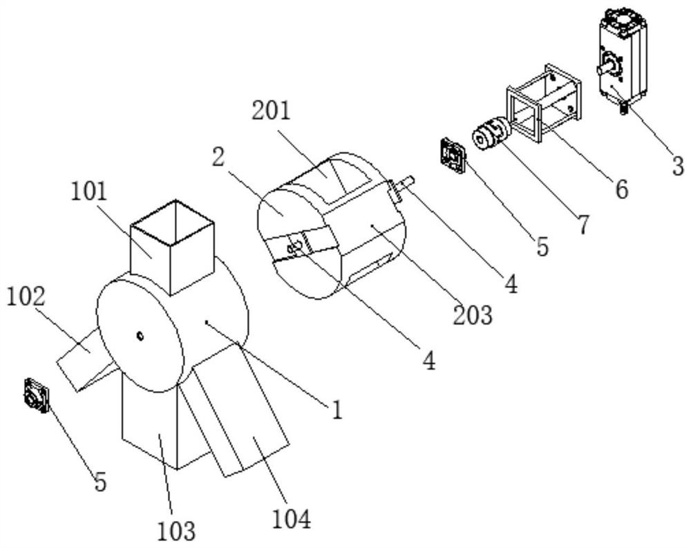
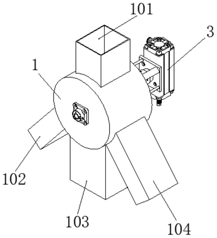
[0025] Such as Figure 1-8 As shown, this embodiment includes a material distribution housing 1, a material distribution rotor 2 arranged in the material distribution housing 1, and a rotating cylinder 3 connected to the material distribution rotor 2, and the seated shaft 4 is assembled on both ends of the material distribution rotor 2. end, and is fixed on the material distribution shell 1 through the bearing with seat 5, so that the material distribution rotor 2 can rotate freely in the material distribution shell 1; the cylinder fixed seat 6 is connected with the rotating cylinder 3, and the cylinder fixed seat 6 is fixed on the On the material housing 1, the rotating cylinder 3 is connected to the belt shaft seat 4 fixed on the material distribution rotor 2 through a coupling 7, and the belt bearing seat 5 is located between the belt shaft seat 4 and the coupling 7, and the rotating cylinder 3 controls the rotation of the material distribution rotor 2, and controls the rot...

Embodiment 2

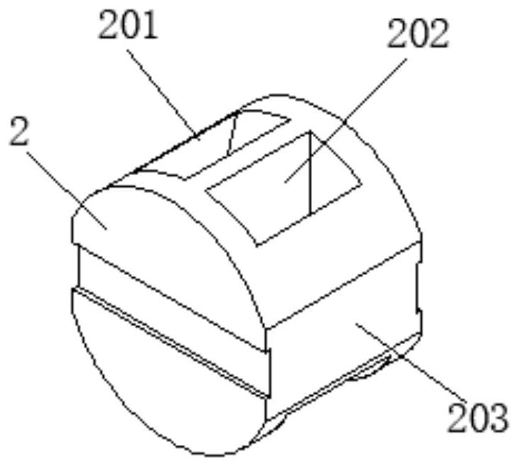
[0029] Such as Figure 7-9 As shown, in this embodiment, the distributing rotor 2 is provided with a through passage, the longitudinal section of which is conical, and the cross-sectional area of ​​the upper end surface of the through passage is larger than the cross-sectional area of ​​the feed port 101, and the distributing rotor 2 goes toward the single The angle of side swing is 30°, and within one swing cycle, the end of the through channel close to the feed port 101 is always connected with the feed port 101, that is, when the distributing rotor 2 swings counterclockwise to the limit position, the penetrating passage The left side of the upper end of the channel will be on the same straight line as the left side of the lower end of the discharge port 101, and the lower end of the through channel will be connected with the first discharge port 102; It is located on the same straight line as the right side of the lower end of the discharge port 101, and the lower end of th...


PUM


Abstract

The invention relates to an automatic material-dividing switching device which comprises a material driving shell, a material dividing rotor arranged in the material dividing shell, and a drive mechanism connected with the material dividing rotor. A feed inlet is formed in the upper part of the material dividing shell; at least two discharge holes are formed in the lower part of the material dividing shell; at least one penetrating channel is arranged on the material dividing rotor; the drive mechanism drives the material dividing rotor to swing reciprocatively; and within one swinging period,the end, close to the feed inlet, of the penetrating channel always communicates with the feed inlet, and the end, far away from the feed inlet, of the penetrating channel communicates with any one discharge hole. The automatic material-dividing switching device provided by the invention is high in automation degree and safe and reliable; and through a backstage logic program and a matched automatic device, automatic feeding and discharging of raw material processes of the ferrite industry can be realized, so that the labor intensity of manual operation is greatly reduced, and the feeding anddischarging efficiency is improved.

Description

technical field [0001] The invention relates to a ferrite manufacturing equipment, in particular to a raw material automatic distributing and converting device. Background technique [0002] In the raw material process of the ferrite industry, the raw powder is divided into different silos through the bucket elevator for storage; The material distribution switching device requires multiple automatic valves to switch and cooperate. The control system is complicated and the cost is high. In the face of a dusty environment, the control valve is prone to failure, resulting in low discharge efficiency. Contents of the invention [0003] The technical problem to be solved by the present invention is to overcome the defects existing in the prior art, provide an automatic switch between the feed channel and different discharge channels, reduce or even eliminate the problems of different brand raw material powder mixing and multiple residues, and at the same time the whole The mec...

Claims


Application Information

Patent Timeline
Patent Type & Authority Applications(China)
IPC IPC(8): B65G65/32B65G69/00B65G47/46
CPCB65G47/46B65G65/32B65G69/00
Inventor 舒书张铁军胡盛青寇清黄小琴
Owner HUNAN AEROSPACE MAGNET & MAGNETO
Why Eureka
Try Eureka