Cement leveling vehicle for road construction

A technology of road construction and cement, which is applied in the field of cement leveling vehicles for road construction, and can solve problems such as poor blood circulation, back pain, time-consuming and labor-intensive problems

Inactive Publication Date: 2020-10-20
陈秀兰
View PDF7 Cites 4 Cited by
  • Summary
  • Abstract
  • Description
  • Claims
  • Application Information

AI Technical Summary

Problems solved by technology

[0002] When laying cement roads, the cement slurry is first poured on the soil surface, and then the cement slurry is compacted and smoothed. At present, the cement slurry is generally manually compacted and smoothed with a trowel, and the cement slurry is pressed manually with a trowel. Usually, it is necessary to bend down and manually move the trowel to compact and smooth the cement slurry. This method is time-consuming and laborious, and the efficiency of compaction and smoothing is relatively low, and the workers are prone to back pain after bending for a long time. It is not conducive to health. In order to prevent back pain, workers will squat down to compact and smooth the cement slurry, but squatting for a long time will cause poor blood circulation in the body, which will easily lead to dizziness

Method used


Image

  • Cement leveling vehicle for road construction
  • Cement leveling vehicle for road construction
  • Cement leveling vehicle for road construction

Examples


Embodiment 1

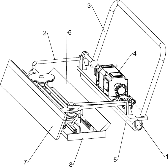
[0024] A cement leveling vehicle for road construction, such as Figure 1-5 As shown, it includes a base plate 1, a connecting frame 2, a handle rod 3, a two-axis servo motor 4, a flattening mechanism 5 and a leveling mechanism 6. The top right side of the base plate 1 is connected with a handle rod 3, and the base plate on the left side of the handle rod 3 1. There are two connecting frames 2 connected to the top, and the two connecting frames 2 are symmetrical front and back. A biaxial servo motor 4 is installed on the top of the bottom plate 1 between the two connecting frames 2. A flattening mechanism 5 is installed on the bottom of the bottom plate 1. The mechanism 5 is connected to the biaxial servo motor 4 through transmission, and a leveling mechanism 6 is installed between the two connecting frames 2, and the leveling mechanism 6 is connected to the flattening mechanism 5 through transmission.

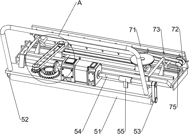
[0025] The flattening mechanism 5 includes a polygonal pressure barrel 51...

Embodiment 2

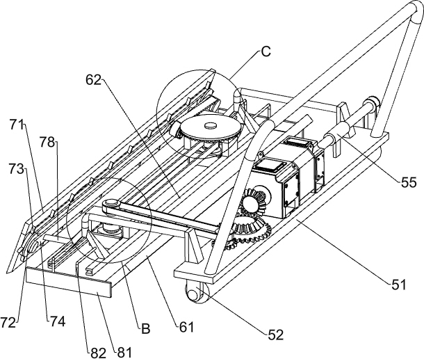
[0029] On the basis of Example 1, such as Figure 1-3 and Figure 6 Shown, also comprise scraping mechanism 7, and scraping mechanism 7 comprises scraper 71, the 4th drive belt set 72, mud removal block 73, fixed plate 74, the 5th drive belt set 75, cylindrical gear 76, crown gear 77 and the first connecting rod 78, the left side of the connecting frame 2 is connected with the first connecting rod 78, the scraper 71 is connected between the left ends of the two first connecting rods 78, between the outer walls of the two first connecting rods 78 A fixed plate 74 is connected between them, the right side of the fixed plate 74 is connected with a fourth drive belt set 72, and a plurality of mud removal blocks 73 are evenly spaced on the belt of the fourth drive belt set 72. A cylindrical gear 76 is rotatably connected to the fixed plate 74, a fifth transmission belt set 75 is connected between the transmission shaft of the cylindrical gear 76 and the rear transmission shaft of ...


PUM


Abstract

The invention relates to a cement leveling vehicle, in particular to a cement leveling vehicle for road construction. The invention aims at solving a technical problem of providing a cement leveling vehicle for road construction, so that cement paste does not need to be manually compacted and leveled by workers. In order to solve the technical problem, the cement leveling vehicle for road construction provided by the invention comprises a bottom plate of which one side of the top is connected with a hand lever, two connecting frames connected to the top, close to the hand lever, of the bottomplate, a double-shaft servo motor mounted at the top, far away from the connecting frame, of the bottom plate, a flattening mechanism being installed at the bottom of the bottom plate and being in transmission connection with the double-shaft servo motor, and a leveling mechanism installed between the connecting frames and being in transmission connection with the flattening mechanism. The polygonal pressing barrel rotates clockwise to compact cement paste, and the leveling plate reciprocates front and back to level the cement paste.

Description

technical field [0001] The invention relates to a cement leveling vehicle, in particular to a cement leveling vehicle for road construction. Background technique [0002] When laying cement roads, the cement slurry is first poured on the soil surface, and then the cement slurry is compacted and smoothed. At present, the cement slurry is generally manually compacted and smoothed with a trowel, and the cement slurry is pressed manually with a trowel. Usually, it is necessary to bend down and manually move the trowel to compact and smooth the cement slurry. This method is time-consuming and laborious, and the efficiency of compaction and smoothing is relatively low, and the workers are prone to back pain after bending for a long time. It is not good for health. In order to prevent back pain, workers will squat down to compact and smooth the cement slurry, but squatting for a long time will cause poor blood circulation in the body, which will easily lead to dizziness. [0003] ...

Claims


Application Information

Patent Timeline
Patent Type & Authority Applications(China)
IPC IPC(8): E01C19/18
CPCE01C19/187
Inventor 陈秀兰
Owner 陈秀兰
Why Eureka
Try Eureka