Wind driven generator blade deicing equipment and wind driven generator blade deicing method

A technology of wind generators and blades, which is applied in the direction of wind power generators, monitoring of wind power generators, control of wind power generators, etc., and can solve problems such as complex blade structures

Active Publication Date: 2020-10-20
SANY ELECTRIC CO LTD
View PDF18 Cites 4 Cited by
  • Summary
  • Abstract
  • Description
  • Claims
  • Application Information

AI Technical Summary

Problems solved by technology

[0013] The purpose of the first aspect of the present invention is to provide a wind turbine blade deicing device, which can solve the technical

Method used


Image

  • Wind driven generator blade deicing equipment and wind driven generator blade deicing method
  • Wind driven generator blade deicing equipment and wind driven generator blade deicing method
  • Wind driven generator blade deicing equipment and wind driven generator blade deicing method

Examples


Embodiment 1

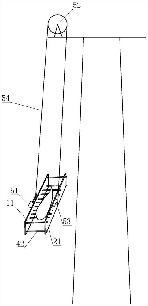
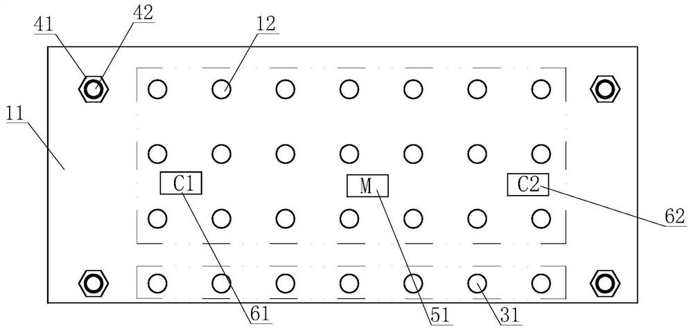
[0054] like Figure 1-Figure 4 As shown, the deicing equipment for wind turbine blades provided in this embodiment includes a deicing device, which is used for detachable connection with the wind turbine blades, and the deicing device has a mechanical deicing head of the first category and a mechanical deicing head of the second category. De-icing head, the first type of mechanical de-icing head is used to install on the windward side of the wind turbine blade, the second type of mechanical de-icing head is used to be installed on the leeward side of the wind turbine blade, the first type of mechanical de-icing The head is connected to the output end of the first type of deicing drive, the second type of mechanical deicing head is connected to the output end of the second type of deicing drive, the fixed end of the first type of deicing device is connected to the second type of deicing drive The fixed end of the device is relatively fixedly arranged.

[0055] By setting the f...

Embodiment 2

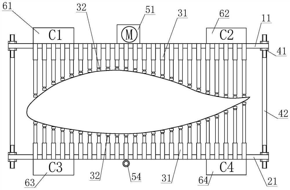
[0076] like Figure 5 shown, refer to Figure 1-Figure 4 The method for deicing wind turbine blades provided in this embodiment uses any of the wind turbine blade deicing equipment described above, including a positioning step, a control step, a deicing step, and a lifting step:

[0077] In the positioning step, the positioning drive device drives the positioning sensor to contact the surface of the wind turbine blade, and transmits a contact signal to the control system; specifically, the positioning hydraulic cylinder 31 drives the pressure sensor 32 to move toward the wind turbine blade, and the pressure sensor located at the front end 32 will be in contact with the blades of the wind power generator first, and when the pressure value borne by the pressure sensor 32 reaches the set value, it means that the blades have been clamped, and the positioning driving device stops working.

[0078] In the control step, the control system receives the signal of the positioning senso...


PUM


Abstract

The invention belongs to the technical field of deicing of wind driven generator blades, and relates to wind driven generator blade deicing equipment and a wind driven generator blade deicing method.The wind driven generator blade deicing equipment comprises deicing equipment body, the deicing equipment body is used for being detachably connected with a wind driven generator blade, the deicing equipment body is provided with a first-class mechanical deicing head and a second-class mechanical deicing head, the first-class mechanical deicing head and the second-class mechanical deicing head areused for being arranged outside the windward side and the leeward side of the blade correspondingly, the first-class mechanical deicing head is connected with the output end of the first-class deicing driving device, the second-class mechanical deicing head is connected with the output end of the second-class deicing driving device, and the fixing end of the first-class deicing device and the fixing end of the second-class deicing driving device are oppositely and fixedly arranged. According to the wind driven generator blade deicing equipment and the wind driven generator blade deicing method, the technical problem that in the prior art, a fixing deicing equipment body needs to be additionally arranged inside the blade, and consequently an internal structure of the blade is caused to becomplex is solved, and the technical effect of simplifying the internal structure of the blade of the wind driven generator is achieved.

Description

technical field [0001] The invention belongs to the technical field of deicing blades of a wind power generator, and in particular relates to a blade deicing device of a wind power generator and a method for deicing a blade of a wind power generator. Background technique [0002] At present, the deicing of wind turbine blades mainly includes the following: [0003] 1. The air in the inner cavity of the blade is heated by the heater, and the blower blows the hot air to circulate in the inner cavity of the blade, and the heat is transferred to the surface of the blade, so that the ice on the surface of the blade gradually melts and falls off; [0004] 2. Combination of heating resistance and ultrasonic oscillation; [0005] 3. There is a built-in heating net in the blade layer, and the heating net works in the freezing state to increase the temperature of the blade surface and make the ice cubes melt and fall off; [0006] 4. Vibration deicing; [0007] At present, the de-i...

Claims


Application Information

Patent Timeline
IPC IPC(8): F03D80/40F03D17/00F03D7/02
CPCF03D7/02F03D17/00F03D80/40Y02E10/72
Inventor 孙找
Owner SANY ELECTRIC CO LTD
Why Eureka
Try Eureka