Accumulator and compressor

A liquid accumulator and compressor technology, which is applied in the field of compressors, can solve problems such as untimely oil return, large noise and vibration of the liquid accumulator, and reduced overall performance of the compressor.

Inactive Publication Date: 2020-10-20
ZHUHAI GREE REFRIGERATION TECH CENT OF ENERGY SAVING & ENVIRONMENTAL PROTECTION
View PDF18 Cites 0 Cited by
  • Summary
  • Abstract
  • Description
  • Claims
  • Application Information

AI Technical Summary

Problems solved by technology

However, when the lubricating oil in the existing liquid reservoir returns to the pump body, the oil return is not complete and the oil is not returned in time, and a large amount of lubricating oil is often stored at the bottom of the liquid reservoir, whi

Method used


Image

  • Accumulator and compressor
  • Accumulator and compressor
  • Accumulator and compressor

Examples


Embodiment Construction

[0033] The following will clearly and completely describe the technical solutions in the embodiments of the present invention with reference to the drawings in the embodiments of the present invention. Apparently, the described embodiments are only some of the embodiments of the present invention, but not all of them. The following description of at least one exemplary embodiment is merely illustrative in nature and in no way taken as limiting the invention, its application or uses. Based on the embodiments of the present invention, all other embodiments obtained by persons of ordinary skill in the art without creative efforts fall within the protection scope of the present invention.

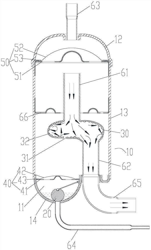
[0034] As shown in the drawings, the embodiment of the present invention provides a liquid accumulator, including: a housing 10 with a housing cavity inside, the bottom of the housing chamber is an oil return area 11, and the bottom of the housing 10 has a return tank. The oil port and air sup...


PUM


Abstract

The invention provides an accumulator and a compressor. The accumulator comprises a shell, a plugging structure and a muffler chamber. The shell is provided with a containing cavity. The bottom of thecontaining cavity is an oil return area. The bottom of the shell is provided with an oil return port and an air supply port. The oil return port communicates with the oil return area. The plugging structure is arranged in the oil return area. At least a part of the plugging structure is movably arranged to avoid or plug the oil return port. The muffler chamber is arranged in the containing cavity. The muffler chamber is provided with a muffler cavity, an air inlet and an air outlet. The air inlet and the air outlet communicate with the muffler cavity, wherein flow cross-sectional area of themuffler cavity is larger than the area of the air inlet and the area of the air outlet. The air outlet communicates with the air inlet. Through the cooperation of the plugging structure and the oil return port, the oil return capacity of the accumulator is improved. The muffler chamber reduces the flow rate of gaseous refrigerants and the collision between the gaseous refrigerants, reduces the airflow excitation vibration of the refrigerants, and thereby reduces the noise and vibration of the accumulator.

Description

technical field [0001] The invention relates to the technical field of compressors, in particular to a liquid accumulator and a compressor. Background technique [0002] The liquid receiver in the compressor is assembled on the suction hole of the pump body. When the volume of the suction cavity of the pump body increases to inhale, the gaseous refrigerant enters the cavity of the liquid storage device, and enters the suction cavity after being filtered by the filter. . When the refrigerant contains lubricating oil and liquid refrigerant, the lubricating oil and liquid refrigerant are continuously deposited into the storage liquid due to the cooperation of the straight pipe and the filter assembly, as well as the flow inertia and gravity of the lubricating oil and liquid refrigerant. the bottom of the device. [0003] The accumulated liquid refrigerant vaporizes as the working conditions of the refrigeration cycle change or absorbs heat from the environment, thus starting ...

Claims


Application Information

Patent Timeline
IPC IPC(8): F04C29/02F04C29/06
CPCF04C29/02F04C29/026F04C29/028F04C29/065
Inventor 张大鹏吴健王珺张心爱闫鹏举
Owner ZHUHAI GREE REFRIGERATION TECH CENT OF ENERGY SAVING & ENVIRONMENTAL PROTECTION
Why Eureka
Try Eureka