Construction method of ballast track-bridge dynamic coupling model

A coupled model and dynamic technology, applied in the field of track construction, can solve the problem that it is difficult to consider the interaction between the ballast bed and the upper and lower structures, it is difficult to simulate the interaction of multi-layer structures, and it is impossible to simulate the plastic deformation of the ballast particle occlusion relationship in the scattered ballast bed, etc. question

Pending Publication Date: 2020-10-20
BEIJING JIAOTONG UNIV
View PDF0 Cites 4 Cited by
  • Summary
  • Abstract
  • Description
  • Claims
  • Application Information

AI Technical Summary

Problems solved by technology

After analysis, the ballasted track model on bridges based on the discrete element method can effectively reflect the characteristics of the bulk medium of the ballasted ballast bed, but it simplifies the sleepers and bridges into fixed walls, which makes it difficult to truly simulate the interaction between multi-layer structures
[0006] The existing numerical simulation methods for ballasted tracks on bridges mainly have the following defects: 1) The finite element method regards the ballasted bed as a homogeneous whole, considers the geometric profile of the ballast bed for unit processing, and the units satisfy

Method used


Image

  • Construction method of ballast track-bridge dynamic coupling model
  • Construction method of ballast track-bridge dynamic coupling model
  • Construction method of ballast track-bridge dynamic coupling model

Examples


Embodiment Construction

[0031] Various exemplary embodiments of the present invention will now be described in detail with reference to the accompanying drawings. It should be noted that the relative arrangements of components and steps, numerical expressions and numerical values ​​set forth in these embodiments do not limit the scope of the present invention unless specifically stated otherwise.

[0032] The following description of at least one exemplary embodiment is merely illustrative in nature and in no way taken as limiting the invention, its application or uses.

[0033] Techniques, methods and devices known to those of ordinary skill in the relevant art may not be discussed in detail, but where appropriate, such techniques, methods and devices should be considered part of the description.

[0034] In all examples shown and discussed herein, any specific values ​​should be construed as exemplary only, and not as limitations. Therefore, other instances of the exemplary embodiment may have dif...


PUM


Abstract

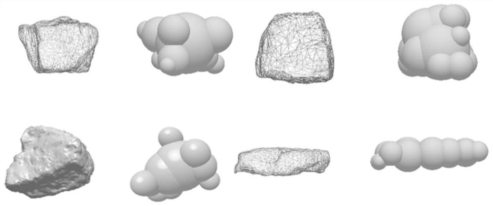
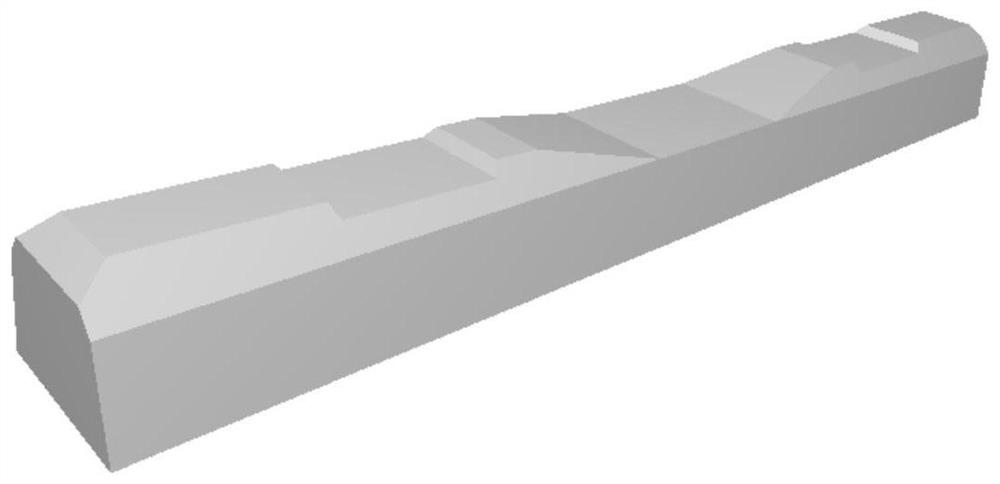
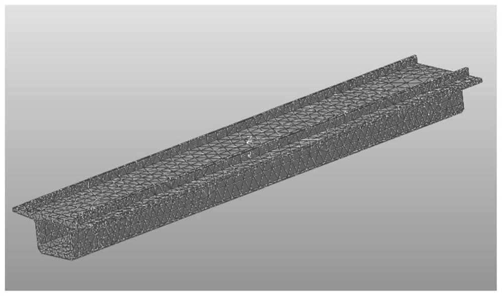
The invention discloses a construction method of a ballast track-bridge dynamic coupling model. The method comprises the steps that a ballast track bed discrete element model reflecting the complex shape and the contact relation of a railway ballast is established through a discrete element method, and the model is used for representing a particle unit accumulation structure, the contact force between particles and coupling surfaces and an equivalent node transplantation load; a continuous medium sleeper finite element model and a bridge finite element model are established by utilizing a multi-body finite element method, wherein the models are used for representing a continuum grid structure, node displacement deformation, surface node position coordinates and an element connection relationship; and a ballast track-bridge dynamic coupling model is constructed based on a discrete element and multi-body finite element coupling method. According to the method, the irregular shape and themutual meshing and stacking relation of the ballasts on the mesoscopic level are fully considered, meanwhile, the interaction between the macroscopic ballast bed and the upper and lower structures can be reflected, and refined simulation of the complex mechanical behaviors of the ballast track on the bridge under the train load effect is achieved.

Description

technical field [0001] The invention relates to the technical field of track construction, and more specifically, to a method for constructing a ballasted track-bridge dynamic coupling model. Background technique [0002] In the process of high-speed railway construction, in order to avoid fertile land and save land, the construction policy of "replacing roads with bridges" was advocated, which made the high-speed railways on bridges huge. For example, the bridge foundation of the Beijing-Shanghai high-speed railway accounts for more than 80% of the entire line. Ballasted track and ballastless track are the main track structure types of high-speed railways. In comparison, ballasted track has the advantages of low cost, low vibration and noise, strong adaptability, and convenient maintenance and repair. Therefore, the main high-speed railways on bridges in my country Application of ballasted track, especially in long bridge sections, ballasted track is an inevitable choice. ...

Claims


Application Information

Patent Timeline
IPC IPC(8): G06F30/13G06F30/23G06T17/10
CPCG06F30/13G06F30/23G06T17/10Y02T90/00
Inventor 高亮石顺伟蔡航蔡小培肖宏侯博文殷浩王向宁韩易昂肖一雄
Owner BEIJING JIAOTONG UNIV
Why Eureka
Try Eureka