
Power acting and power generating all-in-one machine

It is an all-in-one machine and work technology, which is applied in the direction of electrical components, electromechanical devices, etc. It can solve the problems of drop in starting current, increase in torque, and high noise, and achieve the effect of increased torque, reduced use cost, and low noise.

Pending Publication Date: 2020-10-20
立恩(廊坊)新能源科技有限公司
View PDF0 Cites 0 Cited by
  • Summary
  • Abstract
  • Description
  • Claims
  • Application Information

AI Technical Summary

Problems solved by technology

[0005] The beneficial effects of the present invention are: due to the use of the inner rotor of the generator, the outer rotor of the motor and the outer rotor of the three-layer integrated motor for power generation, it can realize multi-pole power supply at the same time, single winding single time, so that the motor In the middle, the starting current is reduced by three times, and the torque is increased, so as to achieve the energy saving effect, and also solve the problem of vibration and noise when starting and braking.

Method used


Image

  • Power acting and power generating all-in-one machine
  • Power acting and power generating all-in-one machine

Examples


Embodiment 1

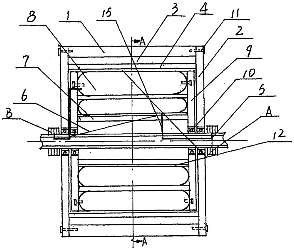
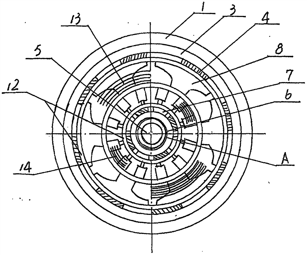
[0008] Embodiment 1: as figure 1 , figure 2 As shown, the two outer end covers 2 of a kind of dynamic work and power generation integrated machine are fixed on both ends of the walking outer wheel shell 1 with bolts 11, and are placed on the hollow shaft 5 with bearings 10, and the fixed strong magnetic silicon steel sheet 3 is fixed on the The inner end of the walking outer wheel shell 1, the rectangular strong magnet 4 of the generator, one N pole and one S pole crossed and equidistantly arranged, are embedded in the inner end of the fixed strong magnetic silicon steel sheet 3, the silicon steel sheet 6 is fixed on the hollow shaft 5, and the strong magnetic 7 One piece of N pole and one piece of S pole are arranged crosswise and equidistantly inlaid on the outer periphery of the silicon steel sheet 6 to form the stator of the generator. Wound in the wire slot of the inner ring of the silicon steel sheet 8 to form the motor rotor.

Embodiment 2

[0009] Embodiment 2: as figure 1 , figure 2 As shown, a slip ring A is provided at the right outer end of the hollow shaft 5 of the integrated machine for power work and power generation, and the three wires 15 of the slip ring A are connected to the coil 14 of the working motor through the inner hole of the hollow shaft 5, and the slip ring B is arranged on the At the left outer end of the hollow shaft 5, the three wires 15 of the slip ring B are connected to the coil 13 of the generator winding through the inner hole of the hollow shaft 5 .

Embodiment 3

[0010] Embodiment 3: as figure 1 , figure 2 As shown, the two inner end covers 9 of the integrated machine for power work and power generation are fixed to both ends of the winding silicon steel sheet 8 with bolts 11, and are placed on the hollow shaft 5 with bearings 10 for movement.


PUM


Abstract

The invention discloses a power acting and power generating all-in-one machine. Two outer end covers (2) are fixed to two ends of a walking outer wheel shell (1) through bolts (11). A bearing (10) ismovably arranged on a hollow shaft (5); a fixed strong magnetic silicon steel sheet (3) is fixed at the inner end of a walking outer wheel shell (1); one N pole and one S pole of a generator rectangular strong magnet (4) are crossed and embedded at the inner end of the fixed strong magnetic silicon steel sheet (3) at equal intervals; a silicon steel sheet (6) is fixed on the hollow shaft (5), theN pole and the S pole of a strong magnet (7) are alternately and equidistantly arranged and embedded at the periphery of the silicon steel sheet (6) to form a generator stator, a power generation winding coil (13) is uniformly wound in a wire groove at the outer ring of a winding silicon steel sheet (8), and an acting motor coil (14) is uniformly wound in the wire groove at the inner ring of thewinding silicon steel sheet (8). Due to the fact that the embedded integration of three-layer acting power generation of the generator inner rotor, the motor outer rotor and the outer-layer rotor is adopted, multi-pole simultaneous acting power supply can be achieved, the weight is light, the size is small, the material cost is reduced, noise is low, and the acting efficiency is high, so that theenergy-saving effect is achieved.

Description

Technical field: [0001] The invention relates to a power acting and generating integrated machine used in an electric vehicle. Background technique: [0002] Energy is an important basic resource for the development of human society. With the development of the world economy, the rapid increase of the world population and the continuous improvement of people's lives, the world's energy demand continues to increase, which has led to increasingly fierce competition for energy resources. The environment Pollution is aggravating and pressure on environmental protection is increasing. At present, the motors used in domestic electric vehicles are generally ordinary permanent magnet motors, which are composed of motors, mechanical transmissions, and deceleration mechanisms. They are heavy and bulky, resulting in increased material costs. The multi-pole convex sub-type design is easy to vibrate when starting and braking, and the noise is large, and most of them are multi-windings w...

Claims


Application Information

Patent Timeline
IPC IPC(8): H02K16/00
CPCH02K16/02
Inventor 聂小平吴立恩
Owner 立恩(廊坊)新能源科技有限公司
Learn More