Test tube cleaning mechanism of water quality detection device and water quality detection device

A water quality detection and cleaning mechanism technology, applied in lighting and heating equipment, dryers, cleaning hollow objects, etc., can solve the problems of poor accuracy of detection results, high cost, manual operation errors and uncertainties, etc.

Active Publication Date: 2020-10-23
哈尔滨跃渊环保智能装备有限责任公司
View PDF20 Cites 3 Cited by
  • Summary
  • Abstract
  • Description
  • Claims
  • Application Information

AI Technical Summary

Problems solved by technology

[0002] Municipal sewage plants and other places require laboratory technicians to test the sewage in and out water samples every day, such as COD, BOD, total nitrogen, total phosphorus and other indicators. The cost of manual testing is relatively high, and due to manual operation errors and There are many uncertainties and the accuracy of the test results is not good
[0003] In order to solve the above problems, automated equipment can be used to assist detection. The automated equipment usually includes a test tube rack. The test tubes on the test tube rack need to be manually removed for cleaning after use, which is cumbersome.

Method used


Image

  • Test tube cleaning mechanism of water quality detection device and water quality detection device
  • Test tube cleaning mechanism of water quality detection device and water quality detection device
  • Test tube cleaning mechanism of water quality detection device and water quality detection device

Examples


Embodiment 1

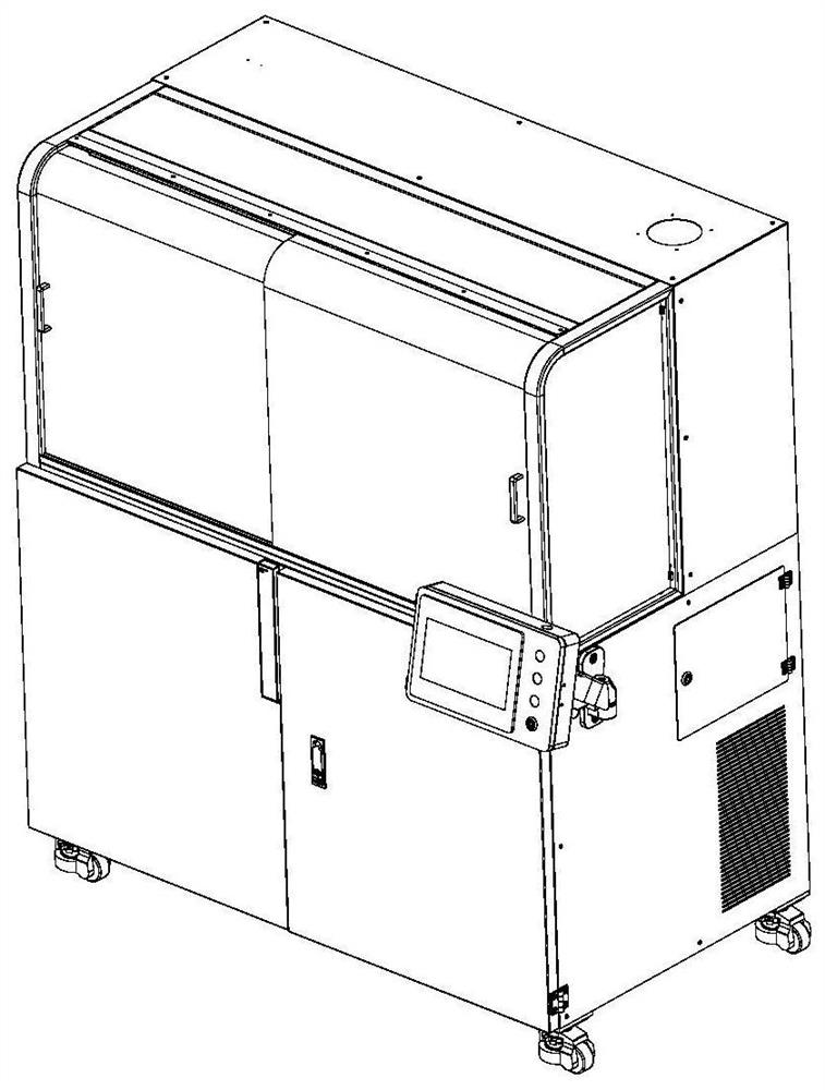
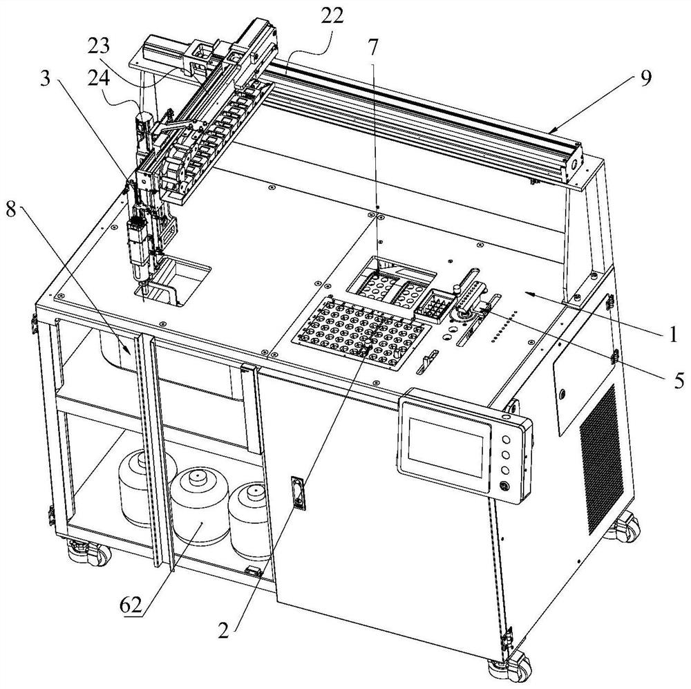
[0068] Such as Figure 1-13 Shown, a kind of water quality detection equipment, can automatically detect water quality, comprises frame 1, is installed on frame 1;

[0069] Storage rack 2, for placing test tube and cuvette 66;

[0070] Mobile grabbing mechanism 3 for grabbing items and taking samples;

[0071] The switch cover mechanism 4 is used to open or close the test tube cover 71 of the test tube;

[0072] The dosing mechanism 5 is used to add medicine to the test tube body 46;

[0073] Shaking mechanism 6, used to fully mix the sample and the medicament;

[0074] Digester 7, used to heat and digest the shaken liquid;

[0075] The detector 8 is used to detect the liquid in the contrast color dish 66 .

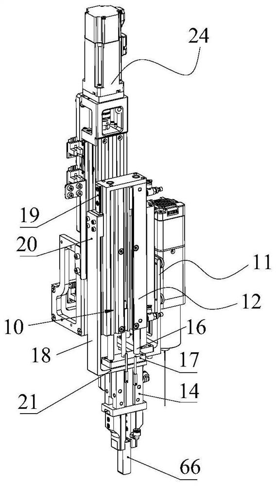
[0076] Such as figure 2 , 3 Shown in and 4, in the present embodiment, mobile grasping mechanism 3 comprises:

[0077] a mobile unit 9;

[0078] The mounting frame 11 is installed on the mobile unit 9;

[0079] The first lifting element 12 is installed on the m...

Embodiment 2

[0160] Such as Figure 17 and 18As shown, the difference between this embodiment and Embodiment 1 is that the digestion apparatus 7 is removed in this embodiment, and a heating element 70 is added on the basis of the shaking mechanism 6 in Embodiment 1 to form a shaking heating mechanism. Such as Figure 17 and 18 As shown, the shake well heating mechanism consists of:

[0161] the first rotating element 43;

[0162] The second rotating element 44 is fixed to the rotating shaft of the first rotating element 43, and the rotating shaft axis of the second rotating element 44 is perpendicular to the rotating shaft axis of the first rotating element 43;

[0163] The test tube self-clamping sleeve 45 is fixed to the rotating shaft of the second rotating element 44 for automatically clamping the test tube body 46 , and the test tube self-clamping sleeve 45 is equipped with a heating element 70 .

[0164] Through the first rotating element 43 and the second rotating element 44 , ...

Embodiment 3

[0171] The difference between this embodiment and embodiment 1 or 2 is that test tube and switch cover mechanism 4 are different, as Figure 19 and 20 As shown, the test tube assembly of this embodiment includes a test tube body 46 and a test tube cover 71. The test tube cover 71 is socketed and fitted with the test tube body 46. The test tube cover 71 includes an inner insertion part 72 and an outer outer part 73 arranged coaxially. An annular groove 74 is formed between the outer portion 72 and the outer sleeve portion 73, and the annular groove 74 is used to be clamped on the opening end of the test tube body 46; the inner insertion portion 72 is a cylindrical structure, and the end of the inner insertion portion 72 has a first tapered shape. Guide surface 75; test tube cover 71 is a flexible material, and the inner sidewall 72 of test tube cover 71 is sealed with the inner wall of test tube body 46, and the outer wall of test tube cover 71 is sealed with the outer wall of ...


PUM


Abstract

The invention discloses a test tube cleaning mechanism of a water quality detection device and a water quality detection device. The test tube cleaning mechanism comprises a storage frame, test tube self-clamping sleeves, a rotating driving piece, a cleaning frame, a first reciprocating element, an air drying frame, a second reciprocating element and a waste liquid box, wherein the test tube cleaning mechanism comprises a storage frame which is rotatably mounted on a rack, and the upper end face of the storage frame is provided with a plurality of fixing grooves; the test tube self-clamping sleeves are fixedly installed in the fixing grooves, and the rotating driving piece is used for driving the storage frame to rotate; the cleaning frame is located below the storage frame, and a plurality of water spraying heads are mounted on the cleaning frame; the first reciprocating element is used for driving the cleaning frame to reciprocate, so that water is sprayed to test tubes fixed on thetest tube self-clamping sleeves; the air drying frame is located below the storage frame, and the air drying frame is provided with a plurality of air blowing heads; the second reciprocating element is used for driving the air drying frame to reciprocate, so that wind is sprayed to the test tubes fixed on the test tube self-clamping sleeves; and the waste liquid box is located below the storage frame and used for receiving waste water. The test tube cleaning mechanism can automatically clean the test tubes.

Description

technical field [0001] The invention relates to the field of water quality detection, in particular to a test tube cleaning mechanism of water quality detection equipment and water quality detection equipment. Background technique [0002] Municipal sewage plants and other places require laboratory technicians to test the sewage in and out water samples every day, such as COD, BOD, total nitrogen, total phosphorus and other indicators. The cost of manual testing is relatively high, and due to manual operation errors and There are many uncertainties, and the accuracy of the test results is not good. [0003] In order to solve the above problems, automated equipment can be used to assist detection. The automated equipment usually includes a test tube rack. The test tubes on the test tube rack need to be manually taken out for cleaning after use, which is relatively cumbersome. Contents of the invention [0004] Aiming at the above problems, the present invention proposes a ...

Claims


Application Information

Patent Timeline
Patent Type & Authority Applications(China)
IPC IPC(8): B08B9/28B08B13/00G01N21/78G01N35/00G01N35/04F26B21/00
CPCB08B9/28B08B13/00G01N21/78G01N35/0099G01N35/04F26B21/004G01N2035/0437
Inventor 李杰
Owner 哈尔滨跃渊环保智能装备有限责任公司
Why Eureka
Try Eureka