
Position clamping and polishing device for automobile part production

A technology for auto parts and polishing devices, which is applied in the direction of grinding drive devices, machine tools for surface polishing, and parts of grinding machine tools, etc. It can solve the problems of inconvenient locking of the device body, impact on the safety of operators, and easy generation of sparks, etc. question

Inactive Publication Date: 2020-10-23
岳文智
View PDF9 Cites 0 Cited by
  • Summary
  • Abstract
  • Description
  • Claims
  • Application Information

AI Technical Summary

Problems solved by technology

[0004] The purpose of the present invention is to provide a clamping polishing device for the production of auto parts to solve the problem that the polishing device proposed in the above background technology needs to be attached to the parts when it is used, so sparks are easily generated, and the operation is easy. The life safety of personnel is affected, and at the same time, the device body also has the problem that the card position is not convenient enough

Method used


Image

  • Position clamping and polishing device for automobile part production
  • Position clamping and polishing device for automobile part production
  • Position clamping and polishing device for automobile part production

Examples


Embodiment Construction

[0016] The following will clearly and completely describe the technical solutions in the embodiments of the present invention with reference to the accompanying drawings in the embodiments of the present invention. Obviously, the described embodiments are only some, not all, embodiments of the present invention. Based on the embodiments of the present invention, all other embodiments obtained by persons of ordinary skill in the art without making creative efforts belong to the protection scope of the present invention.

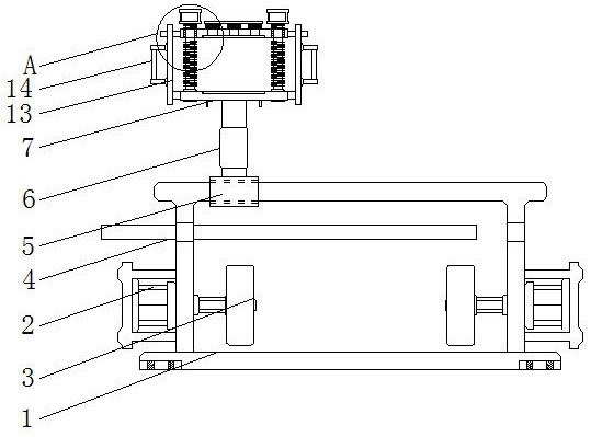
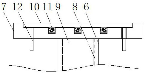
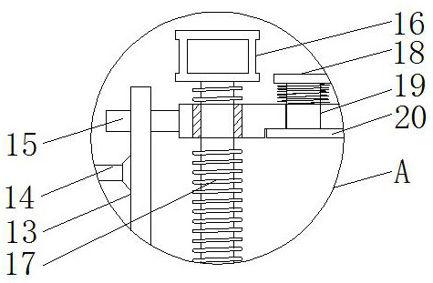
[0017] see Figure 1-3 , the present invention provides a technical solution: a clamping polishing device for the production of auto parts, including a polishing device body 1, a servo motor 2, a polishing disc 3, a shielding and protective diaphragm 4, a sliding seat 5, and a connecting seat 6 , the lower fixing seat 7, the connection adjustment inner groove 8, the position adjustment sliding column 9, the card position receiving plate 10, the spring 11, the ...


PUM


Abstract

The invention discloses a position clamping and polishing device for automobile part production. The position clamping and polishing device for the automobile part production comprises a polishing device body and a linkage adjusting inner groove, wherein servo motors are fixedly connected to the left end and the right end of the polishing device body correspondingly, polishing disks are connectedto the outer sides of the servo motors, the servo motors are symmetrical about the center of the polishing device body, the polishing device body is of an I-shaped structure and is movably connected with a shielding protection transverse partition plate, and the length of the shielding protection transverse partition plate is larger than that of the polishing device body. According to the positionclamping and polishing device for automobile part production, a side connecting batten and a control connecting handle are arranged, a user can better control the side connecting batten convenientlythrough the control connecting handle, then a worker can control the direction of a lower fixing base conveniently, and through sliding between an upper fixing base and the side connecting batten, thedisplacement between the upper fixing base and the lower fixing base can be conveniently adjusted.

Description

technical field [0001] The invention relates to the technical field of automobile processing, in particular to a position polishing device for automobile parts production. Background technique [0002] Polishing refers to the use of mechanical, chemical or electrochemical effects to reduce the surface roughness of the workpiece to obtain a bright and smooth surface. It is a modification of the surface of the workpiece using polishing tools and abrasive particles or other polishing media. Some Finishing operations such as polishing are required when auto parts are processed. [0003] The polishing device on the market needs to be bonded with the parts when it is used, so it is easy to generate sparks, which is easy to affect the life safety of the operator. At the same time, the device body also has the problem that the card position is not convenient enough. For this reason, We propose a clamping position polishing device for auto parts production which has a clamping struc...

Claims


Application Information

Patent Timeline
Patent Type & Authority Applications(China)
IPC IPC(8): B24B29/02B24B41/00B24B41/06B24B47/12
CPCB24B29/02B24B41/007B24B41/06B24B47/12
Inventor 岳文智
Owner 岳文智
Learn More