
Decorative sheet paper pasting device

A technology for decorative boards and stickers, which is applied to adhesive application devices, wooden veneer joints, wood processing appliances, etc. It can solve problems such as complicated operation process, time-consuming and labor-intensive, and difficulty in ensuring the flatness of stickers

Inactive Publication Date: 2020-10-23
刘翠红
View PDF6 Cites 2 Cited by
  • Summary
  • Abstract
  • Description
  • Claims
  • Application Information

AI Technical Summary

Problems solved by technology

[0004] In order to overcome the shortcomings of time-consuming and labor-intensive, difficult to guarantee the flatness of stickers, and complicated operation process, the technical problem is to provide a decorative panel sticker device that reduces time cost, ensures the flatness of stickers, saves the labor of the staff, and automates and simplifies the operation process.

Method used


Image

  • Decorative sheet paper pasting device
  • Decorative sheet paper pasting device
  • Decorative sheet paper pasting device

Examples


Embodiment 1

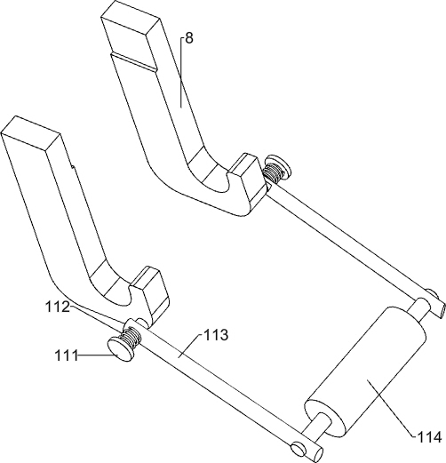
[0044] A decorative panel sticker device such as figure 1 As shown, it includes a base 1, a discharge plate 2, a bracket 3, a discharge frame 4, a glue discharge frame 5, a pushing mechanism 6, a glue brushing mechanism 7, a mounting plate 8 and a first roller 9. The top of the base 1 is connected with a discharge The material plate 2, the front and rear sides of the top of the base 1 are connected with the support 3, the discharge frame 4 is connected between the left part of the support 3, the plastic discharge frame 5 is connected between the right part of the support 3, and the pusher is connected on the left side of the top of the base 1 Mechanism 6, is connected with brushing mechanism 7 between pushing mechanism 6 and glue frame 5, and is connected with mounting plate 8 on the front and rear sides of glue frame 5 right, and first roller 9 is placed between mounting plate 8 bottoms.

[0045] When the staff needs to paste the decorative board, they can first place the dec...

Embodiment 2

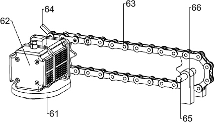
[0047] On the basis of Example 1, such as figure 2 As shown, the pushing mechanism 6 includes a mounting base 61, a motor 62, a chain 63, a push block 64, a first support frame 66 and a first rotating shaft 65, the upper left part of the base 1 is connected with the mounting base 61, and the upper side of the mounting base 61 A motor 62 is connected, three first support frames 66 are connected to the upper left part of the base 1, and a first rotating shaft 65 is rotatably connected between the upper part of the first support frame 66 on the left side and the first support frames 66 on both sides of the right part. , the front end of the first rotating shaft 65 on the left is connected with the output shaft of the motor 62, a chain 63 is connected between the first rotating shaft 65 on both sides, and a push block 64 is connected on the left side of the chain 63 upper side.

[0048] The staff puts the decorative plate into the discharge frame 4, starts the motor 62 to work, t...


PUM


Abstract

The invention relates to a paper pasting device, in particular to a decorative sheet paper pasting device. The invention aims to provide the decorative sheet paper pasting device which lowers the timecost, guarantees the paper pasting flatness, saves the strength of staff and is automatic and simple in operation process. The technical scheme is as follows: the decorative sheet paper pasting device comprises a base, brackets, a pushing mechanism and a brush coating mechanism, wherein the top of the base is connected to an emptying plate; the brackets are connected to two sides of the top of the base, an emptying frame is connected between the upper parts of the brackets, and a glue emptying frame is connected between the brackets on the side close to the emptying frame; the pushing mechanism is connected to the side, close to the emptying frame, of the top of the base; and the brush coating mechanism is connected between the pushing mechanism and the glue emptying frame. By matching amotor, a chain, a push block and a first rotating shaft, a purpose of conveying a decorative sheet is achieved. The decorative sheet paper pasting device is not manually operated and is time-saving and labor-saving.

Description

technical field [0001] The invention relates to a sticker device, in particular to a decorative board sticker device. Background technique [0002] Decorative board is a kind of man-made board. It is a thermosetting laminated plastic made of high-temperature and high-pressure adhesive after chemical treatment with a variety of special papers. The board surface has various wood grains or patterns, bright and flat, bright and beautiful. At the same time, it has good physical properties such as high wear resistance, heat resistance, cold resistance, and fire resistance. The walls and roofs of many high-end houses, well-made cabinets, cabinets, tables, beds, workbenches for precision instruments, laboratory test benches, TV sets, radios and other shells of broadcasting and telecommunications equipment, mostly use this new type of material. Decorative plates. [0003] The decorative board needs to be pasted with wood grain paper during the processing process, while the traditio...

Claims


Application Information

Patent Timeline
IPC IPC(8): B27D1/00B27G11/00
CPCB27D1/00B27G11/00
Inventor 刘翠红
Owner 刘翠红
Learn More