Direct discharge type wastewater treatment device
A wastewater treatment, direct discharge technology, applied in biological treatment devices, multi-stage water treatment, water/sewage treatment, etc., can solve problems such as adsorption and filtration of difficult wastewater
- Summary
- Abstract
- Description
- Claims
- Application Information
AI Technical Summary
Problems solved by technology
Method used
Image

Examples
Embodiment 1
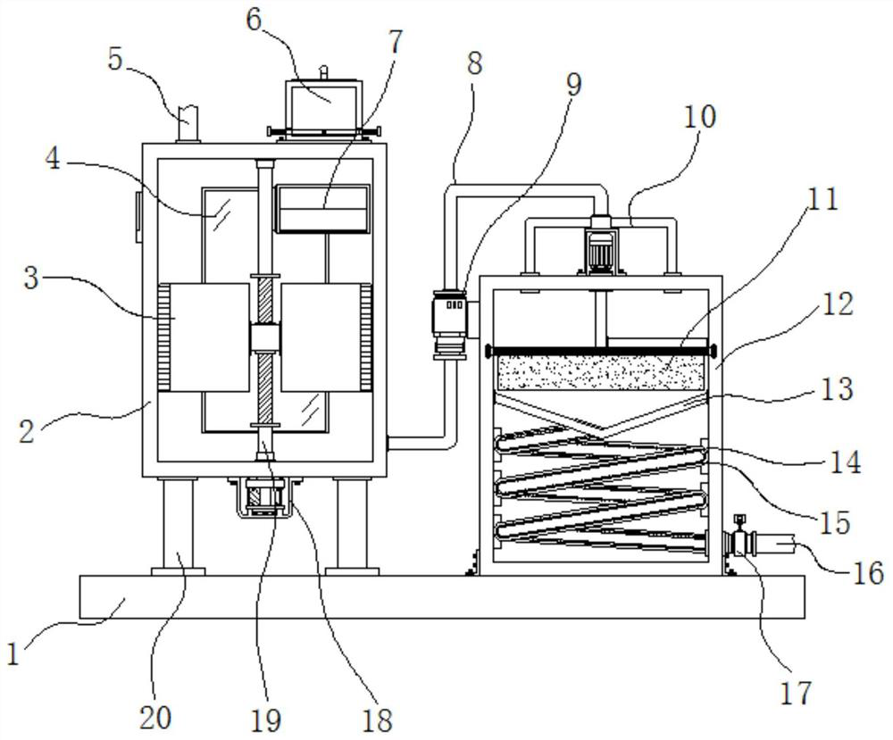
[0035] Example 1: See Figure 1-6 , a straight discharge wastewater treatment device, comprising a base 1, a first housing 2, a connecting pipe 8 and a second housing 12, four corners on the top side of the base 1 are fixedly connected with pillars 20, and the pillars 20 The first shell 2 is fixedly connected between the top ends of the first shell 2, and the bottom end outside the first shell 2 is fixedly connected with a variable frequency motor 18. The model of the variable frequency motor 18 can be YVF-801-4P, and the output end of the variable frequency motor 18 is fixedly connected There is a transmission rod 19, the bottom end on the transmission rod 19 is movably connected with a cleaning mechanism 3, and the top end on the transmission rod 19 is movably connected with a collection mechanism 7, and the inside of the first housing 2 two ends is fixedly connected with a glass plate 4, the first One side of the top of the shell 2 is fixedly connected with the water inlet ...
Embodiment 2
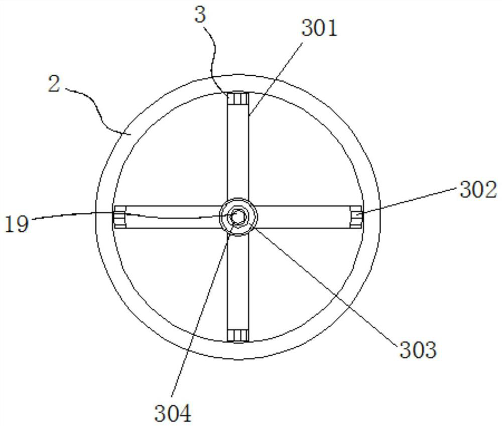
[0038] Embodiment 2: cleaning mechanism 3 is made up of rotating blade 301, steel brush 302, lifting block 303 and thread 304, and thread 304 is evenly arranged on the bottom end on the transmission rod 19, and the outside of transmission rod 19 bottom end is provided with lifting block 303, And the lifting block 303 is evenly and fixedly connected with a rotating blade 301, and one side of the rotating blade 301 is fixedly connected with a steel brush 302;
[0039] The lifting block 303 and the rotating blade 301 are all on the same vertical plane;
[0040] Specifically, such as figure 1 and figure 2 As shown, start the frequency conversion motor 18 to rotate the transmission rod 19, so that the lifting block 303 performs lifting movement under the nesting of the screw thread 304, and the rotating blade 301 whose surface is evenly fixed can promote the separation of the medicament and the waste water inside the first housing 2. Fusion, at the same time the steel brush 302 ...
Embodiment 3
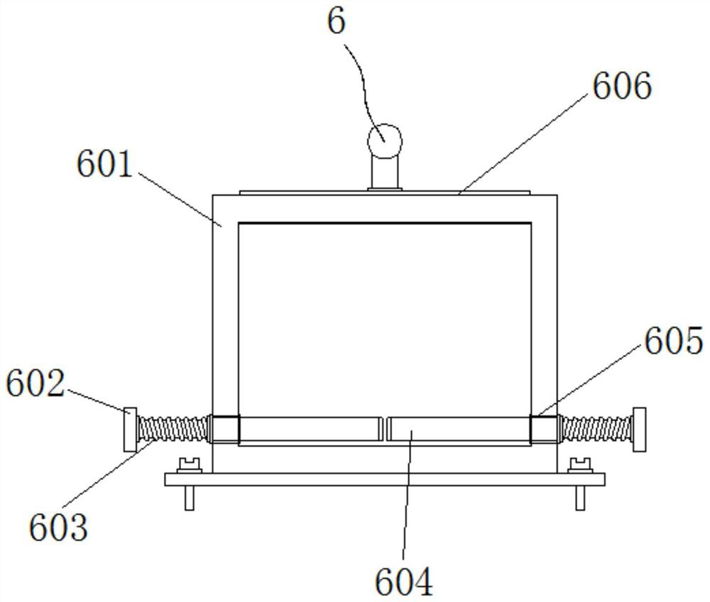
[0041] Embodiment 3: The feeding structure 6 is composed of a storage box 601, a pull rod 602, a return spring 603, a limit plate 604, a movable groove 605 and a top cover 606. The storage box 601 is fixedly connected to a top of the first housing 2. side, the inside of the top of the storage box 601 is provided with a top cover 606, the inside of the bottom of both sides of the storage box 601 is provided with a movable groove 605, and the inside of the movable groove 605 is all provided with a limiting plate 604, and one side of the limiting plate 604 Both ends of each are fixedly connected with a pull rod 602, and a return spring 603 is fixedly connected between the pull rod 602 and one side of the material storage box 601;
[0042] The limiting plates 604 are all on the same horizontal plane, and the return springs 603 and the movable grooves 605 are arranged in concentric circles;
[0043] Specifically, such as figure 1 and image 3 As shown, open the top cover 606 and ...
PUM
 Abstract
Description
Claims
Application Information
 - R&D
- Intellectual Property
- Life Sciences
- Materials
- Tech Scout
- Unparalleled Data Quality
- Higher Quality Content
- 60% Fewer Hallucinations
Browse by: Latest US Patents, China's latest patents, Technical Efficacy Thesaurus, Application Domain, Technology Topic, Popular Technical Reports.
© 2025 PatSnap. All rights reserved.Legal|Privacy policy|Modern Slavery Act Transparency Statement|Sitemap|About US| Contact US: help@patsnap.com