Agricultural biogas digester with desilting function

A biogas digester and functional technology, applied in biochemical cleaning devices, gas production bioreactors, specific-purpose bioreactors/fermentation tanks, etc., can solve the problems of time-consuming and labor-intensive manual dredging, large space occupation, and crusting on the liquid surface And other issues

Active Publication Date: 2020-10-23
程学顺
View PDF6 Cites 0 Cited by
  • Summary
  • Abstract
  • Description
  • Claims
  • Application Information

AI Technical Summary

Problems solved by technology

[0002] At present, biogas as an environmentally friendly energy source has been widely used in our country and even in the world. The slag discharge and dredging in the existing biogas digesters is generally done manually. Manually discharge and desilt the biogas slag, which will easily cause the biogas to be sucked into the human body. Human life is healthy, and manual dredging is time-consuming and laborious. In addition, the liquid surface of the biogas tank is prone to crusting if it is not stirred for a long time, resulting in a decrease in the gas production of the biogas tank. At present, there are also biogas slag discharge dredging devices and Biogas stirring device, but the existing biogas slag discharge dredging device and biogas stirring device are two independent devices, which are installed in the biogas tank and occupy a large space. Therefore, we propose an agricultural Digester

Method used


Image

  • Agricultural biogas digester with desilting function
  • Agricultural biogas digester with desilting function
  • Agricultural biogas digester with desilting function

Examples


Embodiment Construction

[0030] The following will clearly and completely describe the technical solutions in the embodiments of the present invention with reference to the accompanying drawings in the embodiments of the present invention. Obviously, the described embodiments are only some, not all, embodiments of the present invention. Based on the embodiments of the present invention, all other embodiments obtained by persons of ordinary skill in the art without making creative efforts belong to the protection scope of the present invention.

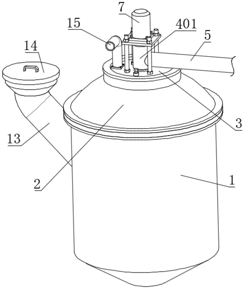
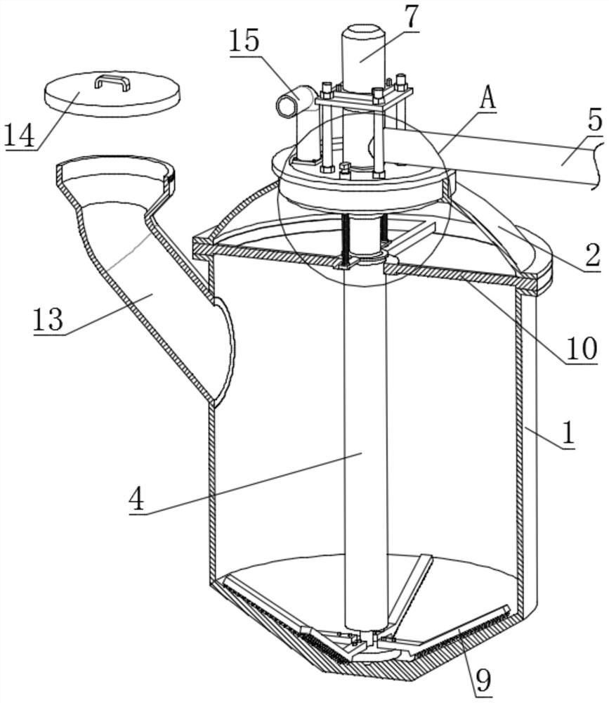
[0031] see Figure 1-11 , the present invention provides a technical solution: an agricultural biogas digester with desilting function, comprising a pond body 1, the upper end of the pond body 1 is provided with an undercut hemispherical gas collection cover 2, such as figure 2 As shown, when biogas is generated inside the pool body 1, the biogas will float upwards to the inside of the gas collecting hood 2, the middle part of the gas collecting hood 2 is pro...


PUM


Abstract

The invention discloses an agricultural biogas digester with a desilting function. The biogas digester comprises a pool body, a gas collecting hood is arranged at the upper end of the tank body, a movable cover is arranged in the middle of the gas collecting hood, a material lifting pipe is arranged in the pool body, a connecting rod is rotationally connected into the material lifting pipe, and the lower end of the connecting rod is fixedly connected to a turbine for driving biogas residues to move upwards in the material lifting pipe. According to the invention, a bolt is rotated, a screw roddrives the connecting pipe to slide downwards, and an upper pipe is communicated with a lower pipe through a connecting pipe. A motor is started, biogas residues at the bottom of the biogas digestercan sequentially move into the conveying pipe along the lower pipe, the connecting pipe and the upper pipe, and the biogas residues are discharged through a conveying pipe; the bolt is rotated to drive the screw rod to drive the connecting pipe to slide upwards, and the connecting pipe is disconnected from the lower pipe; and at the moment, the motor is started, so that the raw materials at the bottom of the biogas digester can be continuously lifted upwards to the upper layer of the raw materials along the lower pipe, and then the stirring effect is achieved.

Description

technical field [0001] The invention relates to the technical field of biogas digester dredging, in particular to an agricultural biogas digester with a dredging function. Background technique [0002] At present, biogas as an environmentally friendly energy source has been widely used in our country and even in the world. The slag discharge and dredging in the existing biogas tanks are generally done manually. Manually discharge and desilt the biogas slag, which is easy to inhale the biogas into the human body and affect the human body. Human life is healthy, and manual dredging is time-consuming and laborious. In addition, if the biogas tank is not stirred for a long time, the liquid surface of the biogas tank is prone to crusting, which leads to a decrease in the gas production of the biogas tank. At present, biogas slag discharge dredging devices and Biogas stirring device, but the existing biogas slag discharge dredging device and biogas stirring device are two devices ...

Claims


Application Information

Patent Timeline
IPC IPC(8): C12M1/107C12M1/02C12M1/00
CPCC12M21/04C12M23/06C12M23/18C12M27/02C12M47/10Y02E50/30
Inventor 程学顺
Owner 程学顺
Why Eureka
Try Eureka