Material conveying device for biogas engineering

A conveying device and feeding device technology, applied in conveyors, mechanical conveyors, transportation and packaging, etc., can solve the problems of high dry matter concentration, reduced surface area, feeding interruption, etc. Solid crust, the effect of ensuring uniformity

Inactive Publication Date: 2018-02-16
南京通用电气装备有限公司
View PDF0 Cites 7 Cited by
  • Summary
  • Abstract
  • Description
  • Claims
  • Application Information

AI Technical Summary

Problems solved by technology

There are a series of problems in this feeding method: 1) It is necessary to set up a premixing tank, which occupies a lot of land and investment, and the odor generated in the premixing tank and fermentation will affect the environment; 2) Due to the large particles of straw, the dry matter concentration High, it will cause blockage and wear of the conveying pipes and pumps. Once the feed pump is blocked, the feed will be interrupted and the continuity of fermentation cannot be satisfied. In addition, there are domestic straws that are directly fed into the In the fermentation tank, this method also has some problems: 1) Due to the high dry matter content of agricultural and forestry straw, it is not easy to store, so water will be added for compaction during the storage process of the silage method, so that the viscosity of the straw used for fermentation is high, and The screw conveyor is not suitable for conveying high-viscosity substances; 2) The use of the screw conveyor cannot ensure that the straw is evenly fed into the fermentation tank. After entering the fermentation tank, there will be local and upper layer of straw accumulation, and in severe cases, a thick floating layer will be formed. On the one hand, The surface area is reduced, which affects the gas production capacity. In severe cases, the biogas in the fermentation tank cannot pass through the scum layer and overflow upwards, which eventually leads to excessive pressure in the liquid area of ​​the tank, resulting in the danger of the fermentation tank bursting

Method used


Image

  • Material conveying device for biogas engineering
  • Material conveying device for biogas engineering
  • Material conveying device for biogas engineering

Examples


Embodiment Construction

[0023] The present invention will be further illustrated below in conjunction with the accompanying drawings and specific embodiments. This embodiment is implemented on the premise of the technical solution of the present invention. It should be understood that these embodiments are only used to illustrate the present invention and are not intended to limit the scope of the present invention.

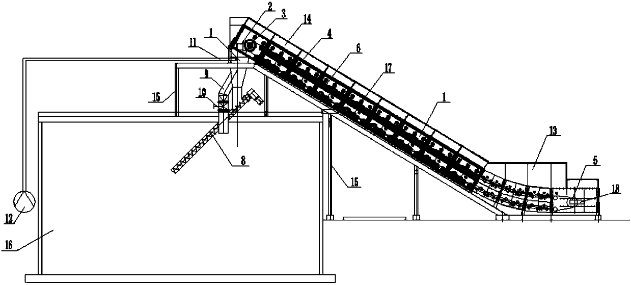
[0024] Such as Figures 1 to 2 As shown, the embodiment of the present invention provides a material conveying device for biogas engineering. The device includes a conveying steel belt machine and an intermediate feeding device. The conveying steel belt machine is obliquely arranged between the top of the fermentation tank 16 and the ground, located The part on the ground is the feed end, and the top is the discharge end. The conveying steel belt machine comprises a frame 1, a driving mechanism 2, a main driving wheel 3, a plurality of supporting rollers 4, a driven wheel 5 and a convey...


PUM


Abstract

The invention discloses a material conveying device for biogas engineering. The device includes a conveying steel belt machine and an intermediate feeding device. The conveying steel belt machine is installed obliquely between the top of the fermenter and the ground. The intermediate feeding device is installed on the top of the fermenter. The upper end of the machine is connected, and the lower side is connected with a screw conveyor, and the lower end of the screw conveyor is arranged below the biogas slurry liquid level in the fermenter. The invention transports the loose straw through the steel belt conveyor, and a baffle plate is arranged on the steel belt conveyor, which ensures the uniformity of the straw conveying and avoids the phenomenon of straw piling and jamming caused by the ordinary belt conveying; by controlling the movement of the steel belt The speed can control the conveying volume of the straw, which is suitable for the adjustment of the feed volume of the biogas project; the straw is in the middle warehouse, mixed with the return biogas slurry sprayed from the spray pipe on the top of the warehouse, and then enters the fermentation tank, which ensures the solid-liquid mixing. Adequacy, avoiding the phenomenon of solid crusting in the tank.

Description

technical field [0001] The invention relates to the field of material conveying devices, in particular to a material conveying device for biogas engineering. Background technique [0002] my country is currently the world's largest energy consumer. Since 2008, my country's dependence on foreign oil has exceeded 50%, and the contradiction between supply and demand is prominent. Energy shortage has become one of the main factors restricting the sustainable and harmonious development of my country's economy, environment and ecology. Biomass energy can not only create economic benefits, help reduce carbon dioxide emissions, alleviate the energy crisis, but also help my country cope with climate change and solve environmental problems. The country pays more attention to the development of biomass energy in the development strategy layout, resource cultivation, energy development, and industrial structure adjustment, and provides policy support. The development potential of my cou...

Claims


Application Information

Patent Timeline
Patent Type & Authority Applications(China)
IPC IPC(8): B65G23/04B65G15/48B65G23/30B65G15/60B65G65/32B65G37/00B65G33/14B65G15/64B65G23/44B65G15/58C12M1/107
CPCB65G23/04B65G15/48B65G15/58B65G15/60B65G15/64B65G23/30B65G23/44B65G33/14B65G37/00B65G65/32C12M21/04
Inventor 孟蓬强
Owner 南京通用电气装备有限公司
Why Eureka
Try Eureka