Orifice flood discharge structure in concrete dam

A technology for concrete structures and concrete dams, applied in dams, water conservancy projects, sea area projects, etc., can solve problems affecting the construction quality of rectangular orifice flood discharge structures, affecting the inspection effect of welding quality, unfavorable vibration and compaction of concrete structures, etc.

Pending Publication Date: 2020-10-23
CHINA HYDROELECTRIC ENGINEERING CONSULTING GROUP CHENGDU RESEARCH HYDROELECTRIC INVESTIGATION DESIGN AND INSTITUTE
View PDF0 Cites 2 Cited by
  • Summary
  • Abstract
  • Description
  • Claims
  • Application Information

AI Technical Summary

Problems solved by technology

[0002] Large and medium-sized concrete dams are equipped with a rectangular orifice flood discharge structure. The rectangular orifice flood discharge structure includes an orifice steel lining arranged along the direction of water flow. Concrete structures are poured around the orifice steel lining. Connect the set steel lining section, the cross-sectional shape of the steel lining section is rectangular, and it is welded by four steel plates in turn, the top plate, the left plate, the bottom plate and the right plate. They are arranged perpendicular to each other, and the weld formed by welding is a fillet weld. The shape of the corner of the fillet weld is irregular and the thickness is inconsistent, which brings difficulties to the accurate detection of ray and other detection methods and affects the welding quality detection effect.
At the same time, there are stress concentrations at the four right-angle corners of the steel lining joint, which is not conducive to the compaction of the concrete structure and affects the construction quality of the rectangular orifice flood discharge structure

Method used


Image

  • Orifice flood discharge structure in concrete dam
  • Orifice flood discharge structure in concrete dam

Examples


Embodiment Construction

[0021] The present invention will be further described below in conjunction with the accompanying drawings and specific embodiments.

[0022] The directions referred to below are figure 2 The orientation of each component is the reference.

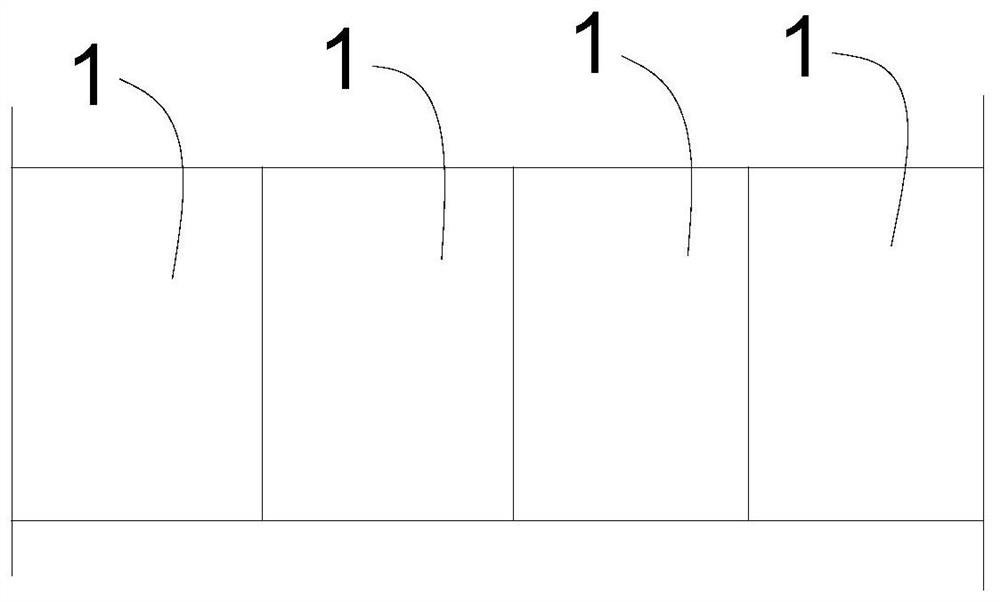
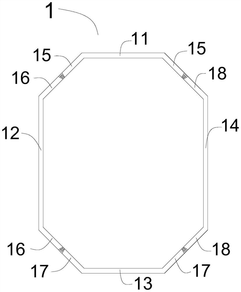
[0023] Such as figure 1 , figure 2 As shown, the orifice flood discharge structure in the concrete dam of the present invention includes an orifice steel lining arranged along the water flow direction, and a concrete structure is poured around the orifice steel lining, and the orifice steel lining includes a plurality of steel lining sections connected in sequence 1. The steel lining section 1 includes a top plate 11, a left side plate 12, a bottom plate 13, and a right side plate 14, and also includes a first connecting flap 15, a second connecting flap 16, a third connecting flap 17, and a fourth connecting flap plate 18, the left and right sides of the top plate 11 are respectively connected with a first connecting flap 15, the fir...


PUM


Abstract

The invention relates to the technical field of concrete dams, in particular to an orifice flood discharge structure in a concrete dam. The structure comprises an orifice steel liner arranged along awater flow direction, wherein a concrete structure is poured around the orifice steel liner, the orifice steel liner comprises a plurality of steel liner sections which are sequentially connected andarranged, and the steel liner sections each comprise a top plate, a left side plate, a bottom plate, a right side plate, a first connecting folded plate, a second connecting folded plate, a third connecting folded plate and a fourth connecting folded plate. Welding seams formed by welding of the components are butt welding seams, the butt welding seams are more convenient for groove cutting and welding construction compared with fillet welding seams formed by welding in the prior art, the thickness of the periphery of the butt welding seams is consistent, the welding quality and reliability are improved, a detection operation surface is a plane, and the detection of the welding quality is also convenient. Moreover, the four corner edges of the steel liner sections are not right angles, sothat the problem of stress concentration at the four right-angle corner edges is avoided, the concrete structure is more favorable for vibrating and compacting, and the construction quality is improved.

Description

technical field [0001] The invention relates to the technical field of concrete dams, in particular to an orifice flood discharge structure in a concrete dam. Background technique [0002] Large and medium-sized concrete dams are equipped with a rectangular orifice flood discharge structure. The rectangular orifice flood discharge structure includes an orifice steel lining arranged along the direction of water flow. Concrete structures are poured around the orifice steel lining. Connect the set steel lining section, the cross-sectional shape of the steel lining section is rectangular, and it is welded by four steel plates in turn, the top plate, the left plate, the bottom plate and the right plate. Arranged perpendicular to each other, the weld formed by welding is a fillet weld. The shape of the corner of the fillet weld is irregular and the thickness is inconsistent, which brings difficulties to the accurate detection of ray and other detection methods and affects the weld...

Claims


Application Information

Patent Timeline
Patent Type & Authority Applications(China)
IPC IPC(8): E02B7/04E02B8/06
CPCE02B7/04E02B8/06
Inventor 刘小强郑付刚贺春晖赖长江
Owner CHINA HYDROELECTRIC ENGINEERING CONSULTING GROUP CHENGDU RESEARCH HYDROELECTRIC INVESTIGATION DESIGN AND INSTITUTE
Why Eureka
Try Eureka