
Automatic drilling fluid-solid phase control system

A phase control and drilling fluid technology, applied in the field of oil drilling, can solve the problems of heavy on-site maintenance workload, inconvenient use, and unpredictability of equipment failures in advance

Pending Publication Date: 2020-10-23
BC P INC CHINA NAT PETROLEUM CORP +1
View PDF0 Cites 4 Cited by
  • Summary
  • Abstract
  • Description
  • Claims
  • Application Information

AI Technical Summary

Problems solved by technology

[0002] At present, the solid control system of domestic oil rigs is equipped with vibrating screens, sand pumps and other electrical equipment. The number is about 35 on average. The on-site maintenance workload is heavy, and all equipment failures cannot be predicted in advance. They are all shut down for maintenance or use backup device
Drilling fluid solid phase control is mostly manual operation. Mud workers need to travel to and from solid control areas according to different drilling fluid performance requirements, manually operate various equipment and valves to adjust mud flow and performance, and manually monitor drilling fluid parameters and various equipment operations. There are problems such as low safety factor, inconvenient use, and poor working environment
The drilling site puts forward higher requirements for the informatization of drilling rigs, and it is urgent to carry out online monitoring and diagnosis technology research of the solids control system to solve the current on-site problems such as the low degree of informatization of the solids control system, the inability to obtain the operating status of the equipment in real time, and the high failure rate of the equipment

Method used


Image

  • Automatic drilling fluid-solid phase control system
  • Automatic drilling fluid-solid phase control system
  • Automatic drilling fluid-solid phase control system

Examples


Embodiment Construction

[0027] In the following description, numerous specific details are given in order to provide a more thorough understanding of the present invention. It will be apparent, however, to one skilled in the art that embodiments of the invention may be practiced without one or more of these details. In other examples, some technical features known in the art are not described in order to avoid confusion with the embodiments of the present invention.

[0028] In order to thoroughly understand the embodiments of the present invention, a detailed structure will be set forth in the following description. It is evident that practice of the embodiments of the invention is not limited to specific details familiar to those skilled in the art. Preferred embodiments of the present invention are described in detail below, however, the present invention may have other embodiments besides these detailed descriptions.

[0029] In the description of the present invention, the orientation or posit...


PUM


Abstract

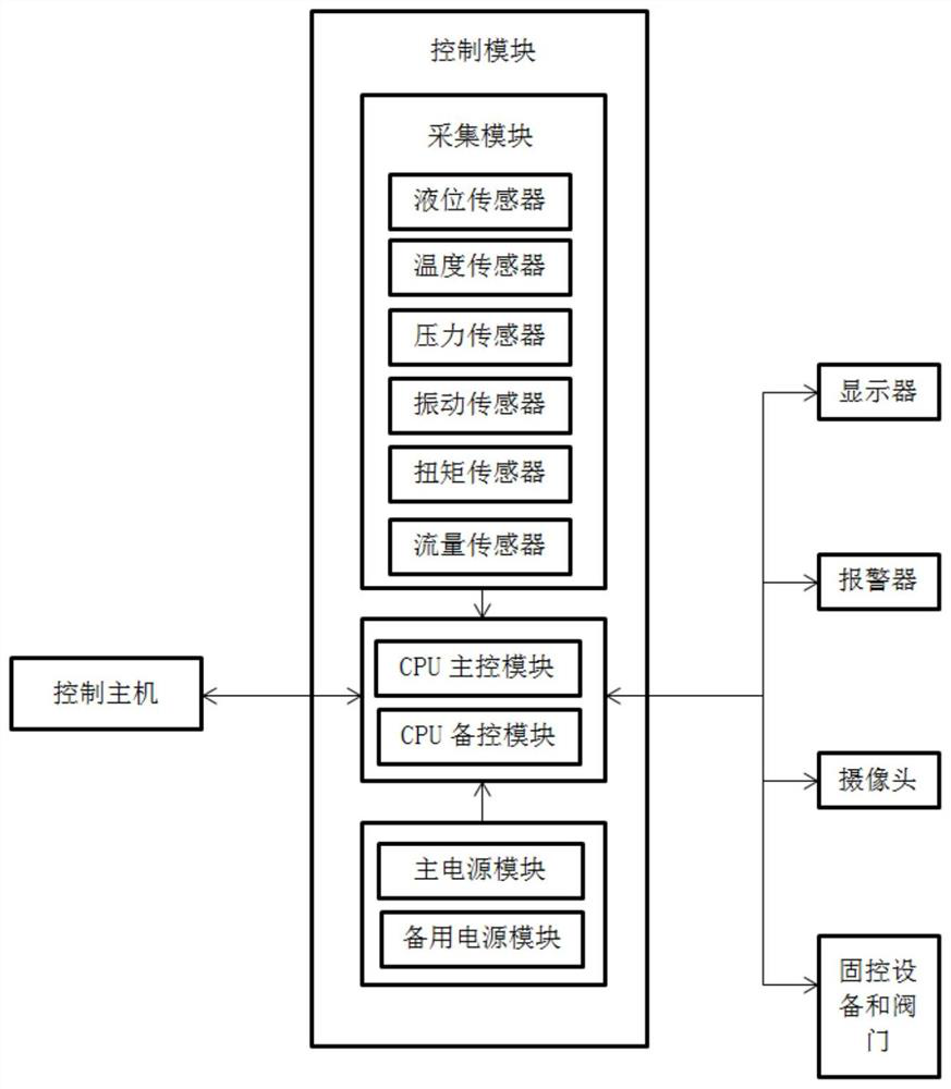
The invention discloses an automatic drilling fluid-solid phase control system. The automatic drilling fluid-solid phase control system comprises an elevated pipe, a solid control tank, a plurality ofsolid control devices, a plurality of valves, a control host, a control module, a displayer, a camera and an alarm, wherein the plurality of solid control devices comprise a vibrating screen, a degasser, a desander, a desilter, a centrifugal machine, a stirrer, a sand pump, a weighting pump and a shearing pump. The control host can be in control connection with all the devices in the system through the control module, the operating states of all the devices in the system can be monitored in real time, centralized control over all the devices and the valves can be achieved, online monitoring is conducted according to collected data, and abnormity alarming can be conducted. The automatic drilling fluid-solid phase control system has the advantages that the structure is simple, design is reasonable, using is convenient, safety and durability are achieved, the device cost is reduced, the labor intensity of manpower is relieved, and the drilling efficiency is greatly improved.

Description

technical field [0001] The invention relates to the technical field of petroleum drilling, in particular to an automatic drilling fluid solid phase control system. Background technique [0002] At present, the solid control system of domestic oil rigs is equipped with vibrating screens, sand pumps and other electrical equipment. The number is about 35 on average. The on-site maintenance workload is heavy, and all equipment failures cannot be predicted in advance. They are all shut down for maintenance or Use a backup device. Drilling fluid solid phase control is mostly manual operation. Mud workers need to travel to and from solid control areas according to different drilling fluid performance requirements, manually operate various equipment and valves to adjust mud flow and performance, and manually monitor drilling fluid parameters and various equipment operations. There are problems such as low safety factor, inconvenient use, and poor working environment. The drilling ...

Claims


Application Information

Patent Timeline
Patent Type & Authority Applications(China)
IPC IPC(8): E21B21/06E21B21/10
CPCE21B21/06E21B21/106
Inventor 王臣樊卫亮高洁周小刚彭爱红张伟罗岚
Owner BC P INC CHINA NAT PETROLEUM CORP
Learn More