Eureka AIR delivers breakthrough ideas for toughest innovation challenges, trusted by R&D personnel around the world.

''U-and-U plus upper corner pump drainage'' stoping surface gas control method

A corner and gas technology, applied in the field of gas control in the "U and U + upper corner extraction" mining face, can solve the problems of large gas emission in the goaf, restricting safe production of the mining face, abnormal gas emission, etc.

Active Publication Date: 2020-10-23
HENAN POLYTECHNIC UNIV
View PDF5 Cites 1 Cited by
  • Summary
  • Abstract
  • Description
  • Claims
  • Application Information

AI Technical Summary

Problems solved by technology

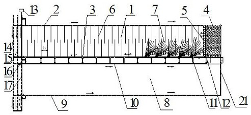
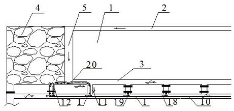
[0003] The invention mainly solves the problem of abnormal gas gushing caused by aggravated air leakage in the goaf when large air volume is introduced into the mining face during multi-lane ventilation, and at the same time solves the problem of low recovery rate caused by too much coal left in the goaf during thick coal seam mining 1. The amount of gas gushing out in the goaf is large, which seriously restricts the safety production of the mining face. A "U and U + upper corner extraction" gas control method for the mining face is proposed, including the "U and U" roadway layout, The construction of underground fixed drainage pumping station system and the common bedding drilling construction of the inlet airway of the mining face, the ordinary bedding drilling construction of the return airway of the mining face, the high-level drilling construction of the inner roof of the return airway of the mining face and the upper corner negative Compressed air duct exhaust method

Method used


Image

  • ''U-and-U plus upper corner pump drainage'' stoping surface gas control method
  • ''U-and-U plus upper corner pump drainage'' stoping surface gas control method

Examples


Embodiment Construction

[0023]The present invention will be clearly described below in conjunction with the drawings and specific embodiments in the embodiments of the present invention. The description here is only used to explain the present invention, but not as a limitation to the present invention. Based on the embodiments of the present invention, all other embodiments obtained by those skilled in the art without creative work, any modifications, equivalent replacements, improvements, etc., shall be included in the protection scope of the present invention Inside.

[0024] Such as Figure 1-2 As shown, the present invention proposes a "U and U + upper corner drainage" gas control method for the mining face, including the "U and U" roadway layout, the construction of the underground fixed drainage pumping station system, and the common air inlet lane of the mining face. Bedding drilling construction, ordinary bedding drilling construction in the return airway of the mining face, high-level dril...


PUM

PropertyMeasurementUnit
Lengthaaaaaaaaaa

Abstract

The invention relates to a ''U-and-U plus upper corner pump drainage'' stoping surface gas control method. The method comprises the steps of U-and-U roadway arrangement, underground fixed extraction pump station system building and stoping surface normal bedding drilling, roof high-position drilling, and upper corner pump drainage arrangement. The manner of U-and-U roadway arrangement comprises two U-shaped ventilation system roadways; extraction is conducted through normal bedding drilling in a stoping surface air inlet roadway and a stoping surface air return roadway as well as roof high-position drilling in the stoping surface air return roadway; a backup surface air return roadway is used for stoping surface assisting air return; an embedded tube is arranged in a goaf and an extractionpipeline is arranged at an upper corner; and goaf embedded tube extraction and stoping surface upper corner extraction are realized. Compared with the prior art, the problem that large air amount isinduced into the stoping surface in case of multi-roadway ventilation so air leakage in mined-out areas is intensified and causes abnormal emission of gas is avoided, and the problems that in thick coal layer mined-out areas, excessive residual coal causes low stoping efficiency and stoping surface safety production is restricted by large emission of the gas in the mined-out areas are solved.

Description

technical field [0001] The patent of the present invention relates to a method of gas control in the mining face of high gassy coal mines, specifically a method of gas control in the mining face of "U and U + upper corner extraction". Background technique [0002] Since the promulgation and implementation of the new "Safe Production Law" (2017), my country's emphasis on safe production has increased year by year. As an important area where accidents are prone to and frequent, coal mines have imposed more stringent regulations on the production of underground coal mines. Regulation. The new version of the "Coal Mine Safety Regulations" (2016) requires that the ventilation of the special gas exhaust lanes and tail lanes be cancelled, and that the return air of the mining face is strictly prohibited from passing through the goaf and the roof fall area, so as to ventilate the gobs that have been used for many years in many coal mines in China. The rectification of the method has...

Claims


Application Information

Patent Timeline
IPC IPC(8): E21F7/00
CPCE21F7/00
Inventor 李宏邓奇根赵发军刘明举魏俊杰
Owner HENAN POLYTECHNIC UNIV
Why Eureka
Eureka Blog
Learn More