Concrete pipe and processing technology thereof

A technology for concrete pipes and pipe bodies, which is applied to pipes, rigid pipes, manufacturing tools, etc., and can solve problems such as rubber rings easily detached from concrete pipes, concrete pipes not tightly sealed, and concrete pipe fluid leakage.

Active Publication Date: 2020-10-23
昆山固特水泥制管有限公司
View PDF20 Cites 3 Cited by
  • Summary
  • Abstract
  • Description
  • Claims
  • Application Information

AI Technical Summary

Problems solved by technology

[0004] The above existing technical solutions have the following defects: after the two socket-type concrete pipes are sealed by the rubber ring, the rubber ring is only inserted between the socket and the socket, and there is no corresponding fixing structure to fix the rubber rin

Method used


Image

  • Concrete pipe and processing technology thereof
  • Concrete pipe and processing technology thereof
  • Concrete pipe and processing technology thereof

Examples


Embodiment 1

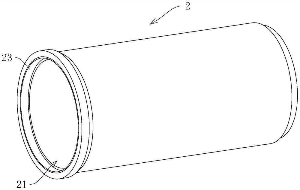
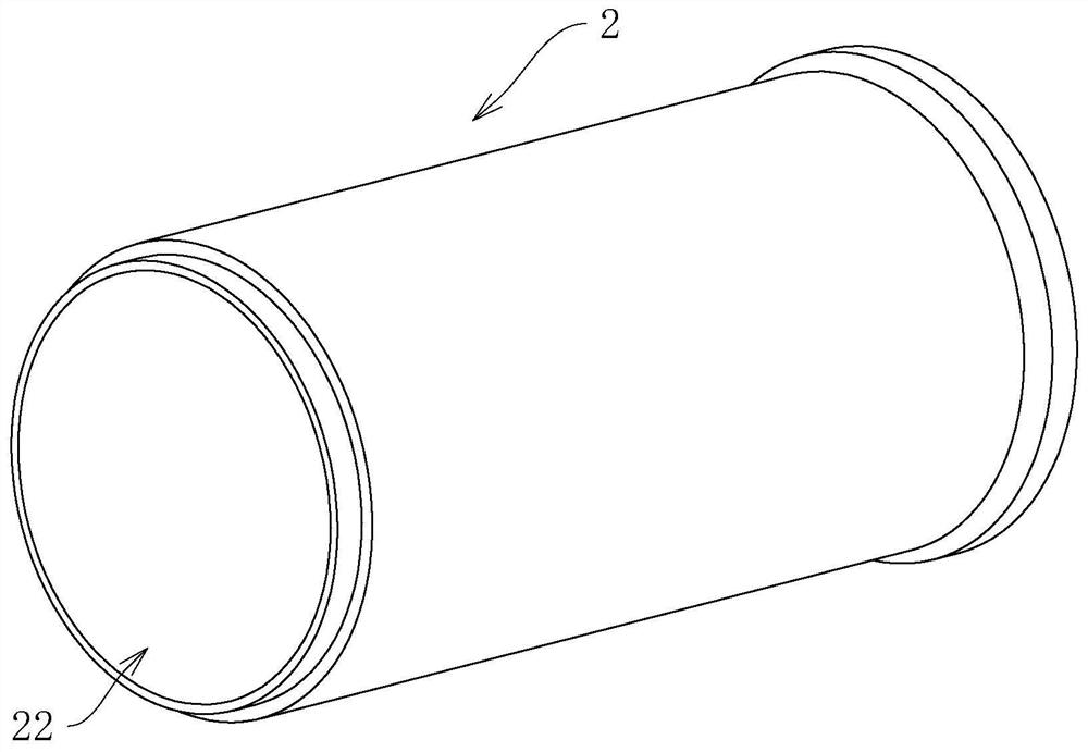
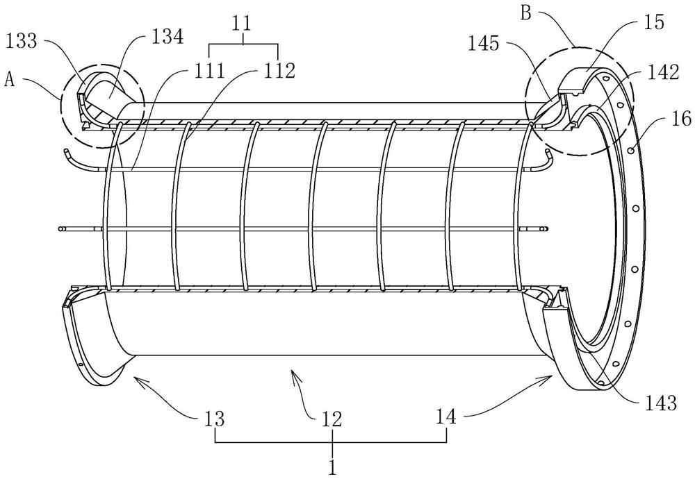
[0048] refer to image 3 , is a concrete pipe disclosed by the present invention, comprising a pipe body 1 and a reinforcement frame 11 arranged in the pipe body 1, the reinforcement frame 11 is formed by welding the main reinforcement 111 and the ring-shaped stiffening reinforcement 112, and the main reinforcement 111 and the reinforcement reinforcement 112 are mutually Vertical mesh. The pipe body 1 includes a middle part 12 and a receiving part 13 and an insertion part 14 respectively located at two ends of the middle part 12, combined Figure 4 and Figure 5The end surface of the receiving part 13 is provided with an annular groove 131, and the end surface of the insertion part 14 is provided with an annular protrusion 141. The section of the protrusion 141 along the axial direction of the pipe body 1 is trapezoidal, and the protrusion 141 The area of ​​the end surface close to the insertion portion 14 is greater than the area of ​​the end surface of the protrusion 141 a...

Embodiment 2

[0056] A processing technology for a concrete pipe based on the concrete pipe in Embodiment 1 disclosed by the present invention includes the following production steps:

[0057] S1: Fabrication of reinforcement frame: vertically weld stiffener 112 on main reinforcement 111, stiffener 112 and main reinforcement 111 are perpendicular to each other to form a mesh, after reinforcement frame 11 is welded and formed, rubber ring 15 and main reinforcement 111 are fixed, and then reinforcement frame 11 is put into in the mold.

[0058] S2: Centrifugation: Start the centrifuge to drive the mold to rotate, and at the same time add concrete to the mold until the centrifuge completes the concrete tube forming.

[0059] S3: finishing treatment: use an iron trowel, a wooden trowel or an aluminum alloy scraper to repeatedly press and wipe the surface of the receiving ring 133 and the connecting ring 144 .

[0060] S3 includes the following sub-steps:

[0061] S31: After the centrifugation...


PUM


Abstract

The invention relates to a concrete pipe and a processing technology thereof. The concrete pipe comprises a pipe body and a steel bar frame arranged in the pipe body. The pipe body comprises a middlepart, a bearing part and an inserting part, wherein the baring part and the inserting part are located at the two ends of the middle part. An annular groove is formed in the end face of the bearing part. An annular protrusion is arranged on the end face of the inserting part. The protrusion corresponds to the groove, and a rubber layer is disposed on the protrusion. The pipe body is provided witha fixing part used for fixing between the bearing part and the inserting part. The concrete pipe has the effect that the sealing performance of a concrete pipe joint is improved.

Description

technical field [0001] The invention relates to the technical field of pipeline transportation, in particular to a concrete pipe and its processing technology. Background technique [0002] Concrete pipes are pipes made of concrete or reinforced concrete for transporting fluids such as water, oil, and gas. It can be divided into plain concrete pipes, ordinary reinforced concrete pipes, self-stressed reinforced concrete pipes and prestressed concrete pipes. When the concrete pipe is produced, it is necessary to first make the steel skeleton and place it in the pipe mold, and then start the centrifuge. The concrete is distributed in the pipe mold under the action of centrifugal force and forms a dense structure. The connection methods of concrete pipes generally include three types: flat pipes, socket joints and tongue and groove joints. [0003] refer to figure 1 and Fig. 2, the two ends of the existing socket-type concrete pipe 2 are socket 21 and socket 22 respectively, ...

Claims


Application Information

Patent Timeline
IPC IPC(8): F16L9/08B28B21/30B28B11/24
CPCF16L9/085B28B21/30B28B11/245
Inventor 周俊华谢中山陈波俞建良宗廷银
Owner 昆山固特水泥制管有限公司
Why Eureka
Try Eureka