Municipal waste incineration device

A waste incineration, municipal technology, applied in incinerators, combustion methods, combustion types, etc., can solve problems such as being unsuitable for municipal engineering, equipment damage, and insufficient incineration

Inactive Publication Date: 2020-10-23
孔金芳
View PDF0 Cites 1 Cited by
  • Summary
  • Abstract
  • Description
  • Claims
  • Application Information

AI Technical Summary

Problems solved by technology

[0003] The existing garbage incineration device directly incinerates the garbage, resulting in insufficient incineration, and the accumulation causes damage to the device, and the existing garbage incineration equipment will produce a lot of polluting gas during inciner...

Method used


Image

  • Municipal waste incineration device
  • Municipal waste incineration device
  • Municipal waste incineration device

Examples


Embodiment 1

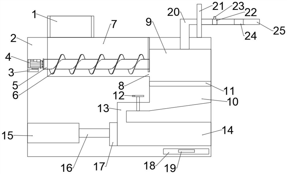
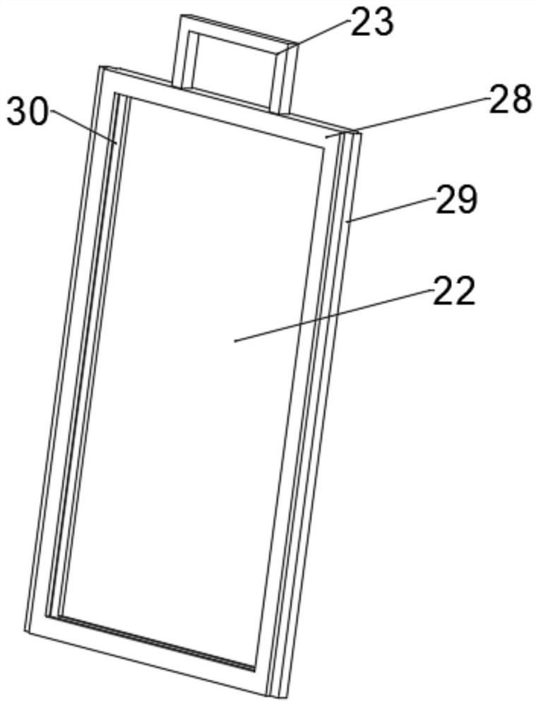
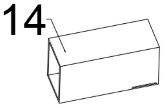
[0033] refer to Figure 1 ~ Figure 4 , a municipal waste incineration device, comprising a box body 2, a feeding box 7 is connected with a bolt on the upper left side of the box body 2, an incineration box 9 is connected with a bolt on the right side of the feeding box 7, and a bolt on the left side of the incineration box 9 is Connected with a transition pipe 13, the end of the transition pipe 13 away from the incineration box 9 is bolted to a compression box 14, the top of the incineration box 9 is bolted to an outlet pipe 20, and the bolt on the outlet pipe 20 is connected to a condensing device 21, and the right side of the condensing device 21 The side bolts are connected with a drying plate 22, the end of the air outlet pipe 20 away from the incineration box 9 is bolted with a purification plate 24, and the side of the purification plate 24 away from the air outlet pipe 20 is bolted with an air outlet 25, and the outside of the drying plate 22 is provided with a limited s...

Embodiment 2

[0041] refer to Figure 5 , a municipal waste incineration device. Compared with Embodiment 1, this embodiment is provided with a running mechanism under the box body 2. The running mechanism includes a rolling wheel 26 and a brake plate 27. The four corners of the box body 2 are connected by bolts. There is a scroll wheel 26, and the bolt on the scroll wheel 26 is connected with a braking plate 27. The rolling wheel 26 is used to make the device move freely, which is convenient for the return and embezzlement of the device. The braking plate 27 is used to keep the device stable when moving to a designated position. Make it not move during operation, ensure its purification effect and increase its applicability.

[0042] Working principle: use the rolling wheel 26 to make the device move freely, which is convenient for the device to be returned to storage and misappropriation; use the brake plate 27 to keep the device stable when moving to the designated position, so that it w...


PUM


Abstract

The invention discloses a municipal waste incineration device. The municipal waste incineration device comprises a box body, wherein a feeding box is arranged on the left side of the upper portion ofthe interior of the box body, an incineration box is arranged on the right side of the feeding box, and a transition pipeline is arranged on the lower portion of the the left side of the incinerationbox; a compression box is arranged at the end, far away from the incineration box, of the transition pipeline, a gas outlet pipe is arranged on the upper portion of the incineration box, a condensingdevice is arranged on the gas outlet pipe, and a drying plate is arranged on the right side of the condensing device; and a purifying plate is arranged at the end, far away from the incineration box,of the gas outlet pipe, and a gas outlet is formed in the side, far away from the gas outlet pipe, of the purifying plate. When the device runs, the drying plate is used for absorbing moisture in waste gas, so that the situation that the purifying effect is affected due to the influence of the moisture on the purifying plate is avoided; due to the fact that the drying plate absorbs the moisture, the drying plate needs to be replaced regularly, a drying pulling plate is pulled out of the gas outlet pipe through a drying handle, and then the drying plate in limiting grooves can be replaced; andthe pulling process is stabler through a sliding table, and the device is suitable for large-scale popularization.

Description

technical field [0001] The invention relates to the technical field of garbage incineration, in particular to a municipal garbage incineration device. Background technique [0002] Municipal engineering refers to the construction of municipal facilities. In my country, municipal facilities refer to various buildings that are set up within the planning and construction scope of urban areas and towns (townships) and provide residents with paid or free public products and services based on government responsibilities and obligations. , structures, equipment, etc. The construction of various public infrastructure supporting urban life belongs to the category of municipal engineering, such as common urban roads, bridges, subways, such as various pipelines closely related to life: rainwater, sewage, water supply, reclaimed water, electricity (outside the red line) Partial), telecommunications, heat, gas, etc., as well as the construction of squares, urban greening, etc., all belon...

Claims


Application Information

Patent Timeline
IPC IPC(8): F23G5/00F23G5/44F23J15/02F23J1/06B60B33/00
CPCB60B33/0002B60B33/0078F23G5/00F23G5/444F23G2205/121F23J1/06F23J15/02
Inventor 孔金芳
Owner 孔金芳
Why Eureka
Try Eureka