Motor overheating protection equipment

An overheating protection and equipment technology, applied in motor control, emergency protection circuit devices, circuits, etc., can solve the problem of low efficiency of motor overheating

Active Publication Date: 2020-10-23
XIANGYANG POWER SUPPLY COMPANY OF STATE GRID HUBEI ELECTRIC POWER +1
View PDF3 Cites 1 Cited by
  • Summary
  • Abstract
  • Description
  • Claims
  • Application Information

AI Technical Summary

Problems solved by technology

[0005] The purpose of the present invention is to solve the problem of low efficiency of motor overheating treatment in the prior art, and propose a kind of motor overheating protection device

Method used


Image

  • Motor overheating protection equipment
  • Motor overheating protection equipment
  • Motor overheating protection equipment

Examples


Embodiment

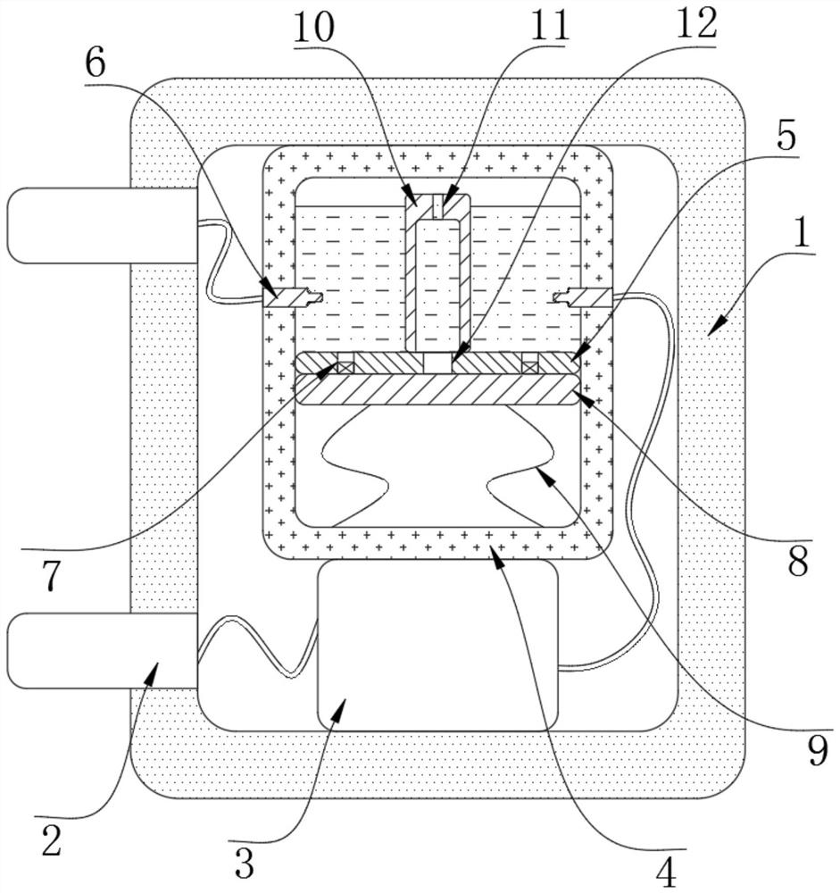
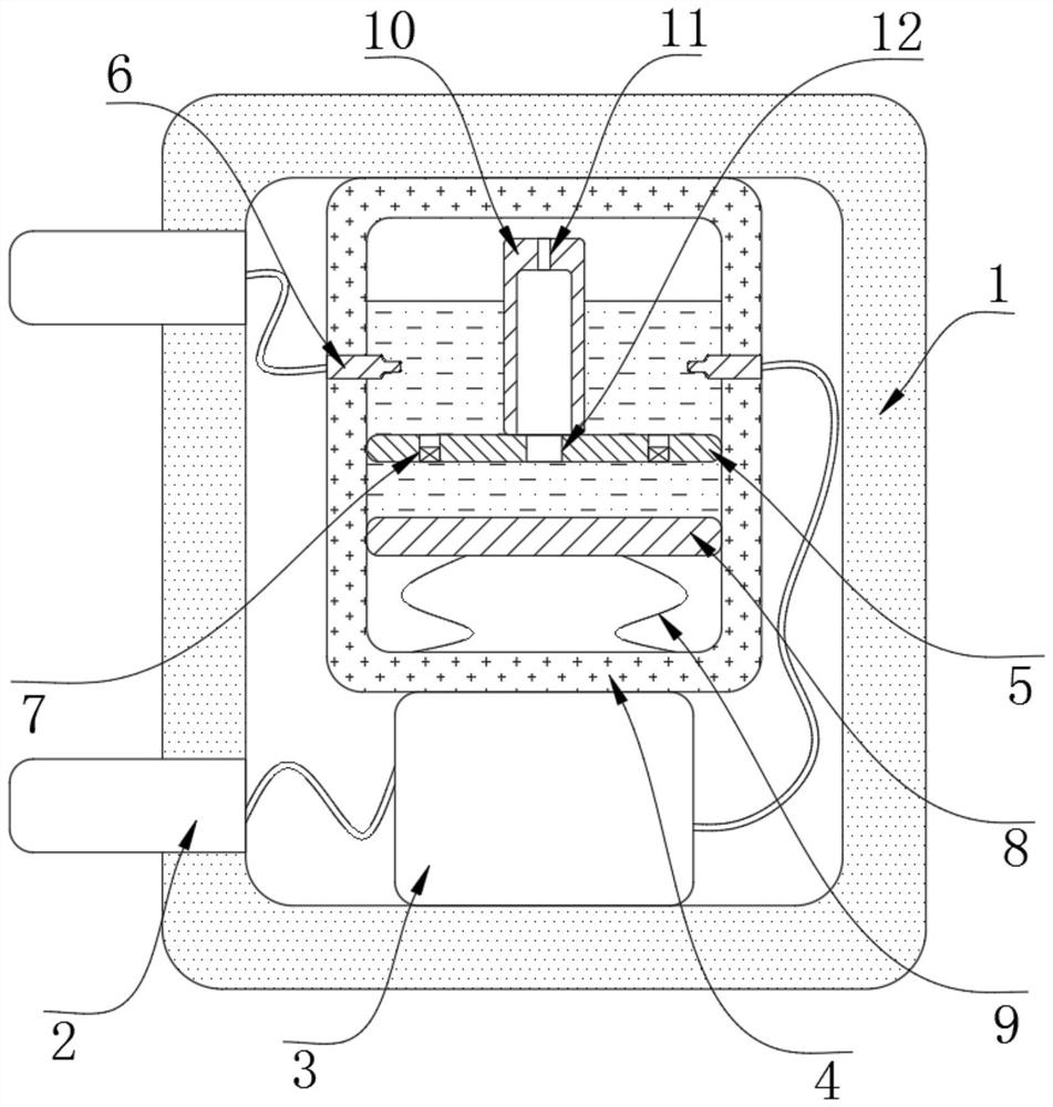
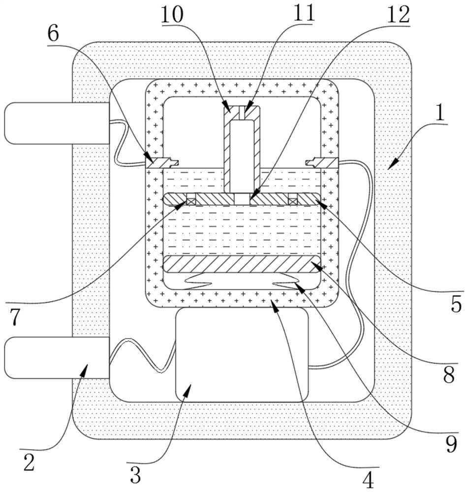
[0019] refer to Figure 1-3 , a motor overheating protection device, including a casing 1, the side wall of the casing 1 is fixed with two symmetrically arranged connection posts 2, the inner bottom of the casing 1 is fixed with an electromagnet 3, and the inner wall of the casing 1 is fixed with a control box 4 , the inner wall of the control box 4 is fixed with a partition 5, the two symmetrical side walls of the control box 4 are penetrated and fixed with two flush connection plates 6, located at the same height, the upper end of the partition 5 is provided with a plurality of speed control Hole 7, the inner bottom of the control box 4 is connected with the suction plate 8 through the return spring 9, the two connecting posts, the electromagnet 3 and the two connecting pieces 6 on the control box 4 are connected by wires to form a loop that is connected to the outside, Used to control the power connection of the motor.

[0020] The upper end of the partition plate 5 is fix...


PUM


Abstract

The invention discloses motor overheating protection equipment. The equipment includes a shell, two symmetrically-arranged power connection columns are fixed to the side wall of the shell in a penetrating mode. An electromagnet is fixed to the inner bottom of the shell. A control box is fixed to the inner wall of the shell, a partition plate is fixed to the inner wall of the control box, two powerconnection pieces arranged in a flush mode are fixed to the two symmetrical side walls of the control box in a penetrating mode, a plurality of speed control holes are formed in the upper end of thepartition plate in a penetrating mode, and a suction plate is connected to the inner bottom of the control box through reset springs. The equipment has the advantages that the electromagnet is arranged to sense the increase of current; the electromagnet generates strong magnetic force under the effect of high current; therefore, a suction plate moves to suck mercury, the amount of electrified mercury is reduced, the electrified cross section is small, the electrified current is reduced, the current of the whole circuit is adjusted, damage to the motor due to high temperature generated by highcurrent is avoided, the current is adjusted in time before high temperature is formed, and high temperature is avoided.

Description

technical field [0001] The invention relates to the technical field of motor protection, in particular to a motor overheat protection device. Background technique [0002] In modern society, human production and labor are inseparable from various motors, and these motors should be used in all fields of all walks of life; [0003] When the motor is driven frequently, a large current will be generated, and an excessively high current will also generate a lot of heat, which will also overheat the motor and cause damage to the motor; when the motor drives the load to move, the load is affected by external resistance. Causes the motor to generate a large locked-rotor current, and the continuous operation of the locked-rotor current will cause the motor to heat up; the commonly used method to protect the motor from overheating is the hardware method, such as connecting the thermistor to the motor. , the resistance of the thermistor increases, which reduces the current of the moto...

Claims


Application Information

Patent Timeline
Patent Type & Authority Applications(China)
IPC IPC(8): H01H1/08H01H3/28H01H29/02H02P29/024H02H7/085
CPCH01H1/08H01H3/28H01H29/02H02P29/027H02H7/0856
Inventor 胡从勇
Owner XIANGYANG POWER SUPPLY COMPANY OF STATE GRID HUBEI ELECTRIC POWER
Why Eureka
Try Eureka