
Photovoltaic power generation device with DC/DC converter

A photovoltaic power generation and converter technology, applied in the field of photovoltaic power generation, can solve the problems of inability to adjust photovoltaic panels, inconvenience for photovoltaic panels to receive sunlight, photovoltaic power generation voltage conversion, etc.

Inactive Publication Date: 2020-10-23
杨国丽
View PDF6 Cites 0 Cited by
  • Summary
  • Abstract
  • Description
  • Claims
  • Application Information

AI Technical Summary

Problems solved by technology

Therefore, an object of the present invention is to provide a photovoltaic power generation device with a DC / DC converter, which can solve the problem of using the device for photovoltaic power generation voltage conversion, and the position of the photovoltaic panel cannot be adjusted according to the orientation of the sun, which is not convenient for photovoltaic Good problem receiving sunlight

Method used


Image

  • Photovoltaic power generation device with DC/DC converter
  • Photovoltaic power generation device with DC/DC converter
  • Photovoltaic power generation device with DC/DC converter

Examples


Embodiment 1

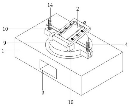
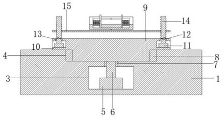
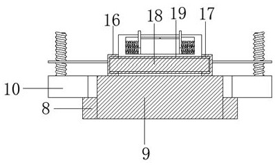
[0027] Such as figure 1 , figure 2 , image 3 with Figure 4 as shown,

[0028]A photovoltaic power generation device with a DC / DC converter, comprising a mounting base 1 and a photovoltaic panel 2, the side of the mounting base 1 is provided with an installation through slot 3, the center of the top of the installation base 1 is provided with a turning slot 4, and the installation through slot 3. A motor 5 is arranged at the center of the bottom end. The output end of the motor 5 is connected to a rotating shaft 6. The top of the rotating shaft 6 and the bottom end of the rotating groove 4 are on the same horizontal plane. A bearing 7 is arranged at the center of the top of the installation through groove 3. The height of the bearing 7 is equal to that of the installation through groove. The vertical distance between the top of 3 and the bottom of the turning groove 4, the bearing 7 runs through the installation through groove 3 and the turning groove 4, the inner wall of...

Embodiment 2

[0030] Such as figure 1 , Figure 4 with Figure 5 As shown, embodiment two is a further improvement on embodiment one.

[0031] The top of the mounting plate 19 is provided with a placement groove 20, the depth of the placement groove 20 is greater than half of the thickness of the mounting plate 19, and the center of the placement groove 20 is provided with a spring 21 relative to the center of the inner wall. The springs 21 have six groups and are arranged symmetrically and equidistantly in three groups. The end portion is fixed with a clip bar 22, the length of the clip bar 22 is equal to the length of the placement groove 20, the height of the clip bar 22 is slightly greater than the depth of the placement groove 20, the center of the side of the placement groove 20 is provided with a perforation 23, and the top of the turntable 9 is provided with a moment groove 24. Both the inner wall of the perforation 23 and the inner wall of the groove 24 are provided with an insul...


PUM


Abstract

The invention relates to the technical field of photovoltaic power generation, in particular to a photovoltaic power generation device with a DC / DC converter. The photovoltaic power generation devicecomprises a mounting rectangular base and a photovoltaic panel, wherein mounting through grooves are formed in the side surfaces of the mounting rectangular base; rotating grooves are formed in the centers of the top ends of the mounting rectangular grooves; a motor is arranged in the bottom center of each mounting through groove; a motor output end is connected with a rotating shaft; a rotating bearing is arranged on the inner wall of each mounting groove; each rotating bearing is rotationally connected with a turntable; top ends of the rotating shafts are connected with bottom ends of the turntables through bearings; mounting frames are arranged at the top ends of the side walls of the turntables; a servo motor is arranged in each mounting frame; an output end of each servo motor is connected with a servo rotating shaft; a matching bearing is arranged on the top wall of each mounting frame; the top end of each servo shaft is connected with a screw in a rotated manner through a matching bearing, and the outside of the screw is connected with a limit plate in a screwed manner; two sets of side plates are symmetrically fixed to one side of the top end of each turntable; connecting bearings are embedded in the centers of the side faces of the side plates; a rotary rod is rotatably connected between the connecting bearings in pair; a mounting plate is fixed to the outer wall of each rotary rod; and an accommodating groove is formed in the top end of each mounting plate.

Description

technical field [0001] The invention relates to the field of photovoltaic power generation, in particular to a photovoltaic power generation device with a DC / DC converter. Background technique [0002] Photovoltaic power generation is a technology that directly converts light energy into electrical energy by using the photovoltaic effect of the semiconductor interface. It is mainly composed of three parts: solar panel components, controllers and inverters. The main components are composed of electronic components. Solar energy After the batteries are connected in series, they are encapsulated and protected to form a large-area solar cell module, and then cooperate with power controllers and other components to form a photovoltaic power generation device. The main principle of photovoltaic power generation is the photoelectric effect of semiconductors. When a photon irradiates a metal, its energy can be completely absorbed by an electron in the metal. The energy absorbed by ...

Claims


Application Information

Patent Timeline
IPC IPC(8): H02S20/30F24S30/452H02S30/00H02S40/32H02S40/34H02S40/30
CPCF24S30/452F24S2030/11F24S2030/135F24S2030/15H02S30/00H02S20/30H02S40/30H02S40/32H02S40/34Y02E10/47Y02E10/50
Inventor 杨国丽
Owner 杨国丽
Learn More