Landscape flowerpot for municipal road

A technology for municipal roads and flowerpots, applied in the field of landscape flowerpots for municipal roads, which can solve the problems of death due to lack of water, inability to realize automatic water replenishment, and inability of plants to absorb water by themselves

Inactive Publication Date: 2020-10-27
张有志
View PDF0 Cites 2 Cited by
  • Summary
  • Abstract
  • Description
  • Claims
  • Application Information

AI Technical Summary

Problems solved by technology

[0003] At present, there are still some deficiencies in the existing landscape flowerpots. Since the bottom of the flowerpot directly separates the plants from the ground, the plants cannot absorb the water in the soil on the ground by themselves, and cannot automatically replenish water. T...

Method used


Image

  • Landscape flowerpot for municipal road
  • Landscape flowerpot for municipal road
  • Landscape flowerpot for municipal road

Examples


Embodiment 1

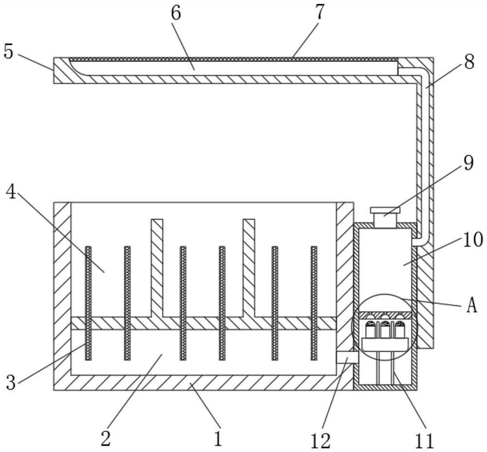
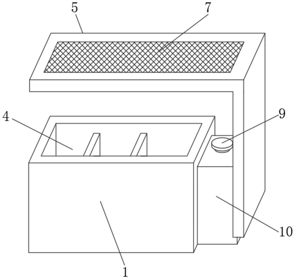
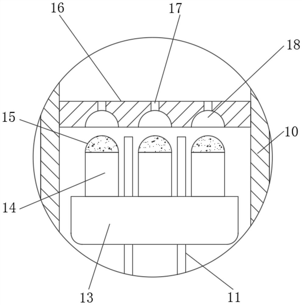
[0028] refer to Figure 1-3 , a landscape flowerpot for municipal roads, comprising a flowerpot main body 1, a water storage cavity 2 and a planting cavity 4 are respectively arranged inside the flowerpot main body 1, and the planting cavity 4 is located above the water storage cavity 2, and the flowerpot main body 1 A cotton sliver 3 is also provided inside of the flower pot, one end of the cotton sliver 3 is arranged in the water storage chamber 2, and the other end of the cotton sliver 3 is arranged in the planting chamber 4, and a water tank 10 is arranged on one side of the outer wall of the flowerpot main body 1, and One side outer wall of the water tank 10 is connected with the water storage chamber 2 through the water replenishing pipe 12, the top outer wall of the water tank 10 is provided with a water adding pipe 9, and the inner wall of the water adding pipe 9 is threadedly connected with an end cap, and the inside of the water tank 10 is provided with a water replen...

Embodiment 2

[0035] refer to Figure 4 , a landscape flower pot for municipal roads. Compared with Embodiment 1, this embodiment also includes a filter screen 19 fixedly connected to the inner wall of the planting cavity 4, and a filter cotton 20 is placed on the top outer wall of the filter screen 19, and the adjacent planting The cavities 4 communicate with each other through a communication hole 21 , and a drain pipe 22 is provided on one side of the outer wall of the flowerpot main body 1 , and one end of the drain pipe 22 communicates with the water storage chamber 2 .

[0036]Working principle: in rainy days, rainwater will fall into the planting cavity 4 from the side, excess rainwater can leak out through the filter screen 19 in the planting cavity 4, and the filter cotton 20 on the filter screen 19 can stop the soil to avoid soil loss, The excess rainwater will flow to the bottom of the planting cavity 4, and the adjacent planting cavity 4 is connected through the communication ho...


PUM


Abstract

The invention discloses a landscape flowerpot for a municipal road. The landscape flowerpot comprises a flowerpot main body, wherein a water-storing cavity and planting cavities are respectively formed in the flowerpot main body, and the planting cavities are located above the water-storing cavity; cotton strips are further arranged in the flowerpot main body, one ends of the cotton strips are arranged in the water-storing cavity, and the other ends of the cotton strips are arranged in the planting cavities; a water tank is arranged on the outer wall of one side of the flowerpot main body, andthe outer wall of one side of the water tank communicates with the water-storing cavity through a water-replenishing pipe; a water supplying pipe is arranged on the outer wall of the top of the watertank, and an end cover is connected to the inner wall of the water supplying pipe through threads; and a water-replenishing mechanism is arranged in the water tank and comprises a partition board, limiting rods, a floating block and rubber balls. Automatic water supply of the landscape flowerpot is effectively realized, and the landscape flowerpot does not need to be usually and manually wateredand irrigated, so that the labor is greatly saved, a use effect is better, and meanwhile, the situation that plants are drowned due to excessive water replenishing can be avoided.

Description

technical field [0001] The invention relates to the technical field of municipal road beautification, in particular to a landscape flower pot for municipal roads. Background technique [0002] Landscape flowerpot is a kind of container for cultivating flowers and trees. It is often used in streets, communities, parks and large amusement parks. It not only protects the growth of flowers and trees, but also plays an aesthetic role. It is an indispensable decoration for urban construction. , and in the construction process of municipal roads, landscape flower pots are often erected on both sides of the road to achieve the purpose of beautifying the road. [0003] At present, there are still some deficiencies in the existing landscape flowerpots. Because the bottom of the flowerpot directly separates the plants from the ground, the plants cannot absorb the water in the soil on the ground by themselves, and cannot realize automatic water replenishment. Therefore, sanitation worke...

Claims


Application Information

Patent Timeline
IPC IPC(8): A01G9/02A01G27/06E03B3/02
CPCA01G9/02A01G27/06E03B3/02Y02A20/108
Inventor 张有志
Owner 张有志
Why Eureka
Try Eureka