
Chemical processing waste gas purification tower

A technology of chemical processing and purification tower, which is applied in the direction of chemical instruments and methods, dispersed particle filtration, and the use of liquid separation agent, etc., can solve the problems of reducing the purification effect of the purification tower, environmental damage of the purification tower, and insufficient interception of the purification tower, etc. Achieve the effects of improving effect and efficiency, improving work efficiency, and improving the degree of purification

Pending Publication Date: 2020-10-27
朱文艳
View PDF9 Cites 6 Cited by
  • Summary
  • Abstract
  • Description
  • Claims
  • Application Information

AI Technical Summary

Problems solved by technology

[0003] In the process of realizing the present invention, the inventor found that at least the following problems in the prior art have not been solved: 1. When the existing chemical waste gas purification tower purifies the chemical waste gas, because the waste gas will contain certain granular objects, When it passes through the purification tower, the interception of the purification tower is not sufficient, and the exhaust gas flutters in the purification tower, causing solid waste to adhere to the inner wall of the purification tower, destroying the environment in the purification tower and reducing the purification efficiency of exhaust gas in the purification tower; 2. The existing purification tower is spraying the liquid purification agent on the waste gas, but the waste gas will flow with the air flow, so that the contact between the waste gas and the purification agent is not sufficient, and the purification effect of the purification tower is reduced

Method used


Image

  • Chemical processing waste gas purification tower
  • Chemical processing waste gas purification tower
  • Chemical processing waste gas purification tower

Examples


Embodiment Construction

[0026] The following will clearly and completely describe the technical solutions in the embodiments of the present invention with reference to the accompanying drawings in the embodiments of the present invention. Obviously, the described embodiments are only some of the embodiments of the present invention, not all of them. Based on the embodiments of the present invention, all other embodiments obtained by persons of ordinary skill in the art without making creative efforts belong to the protection scope of the present invention.

[0027] see Figure 1 to Figure 6 , the present invention provides a technical solution:

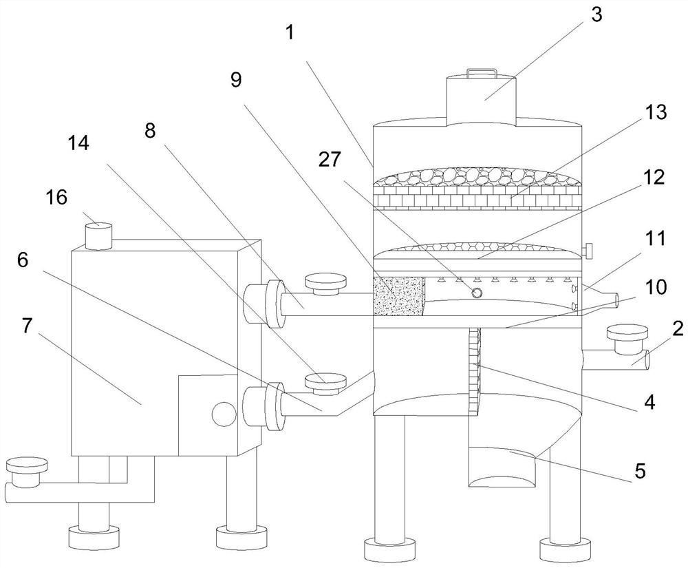
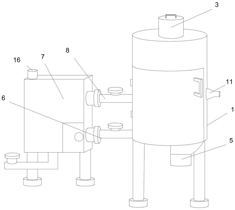
[0028] A chemical processing exhaust gas purification tower, comprising a tank body 1, an air inlet 2 is fixedly installed on the lower part of the outer surface of the tank body 1, an air outlet 3 is fixedly installed on the outer surface of the upper end of the tank body 1, the tank body 1 The inner lower part of 1 is fixedly installed with a vertical fil...


PUM


Abstract

The invention discloses a chemical processing waste gas purification tower comprising a tank body, an air inlet is fixedly formed in the lower part of the outer surface of the tank body; an air outletis fixedly formed in the outer surface of the upper end of the tank body; a vertical filter screen is fixedly installed on the lower portion of the inner side of the tank body, a falling groove is fixedly formed in the position, close to one side of the air inlet, of the lower end of the inner side of the tank body, a partition plate is fixedly connected to the outer surface of the upper end of the filter screen, and an air inlet pipeline is fixedly installed at the position, away from the air inlet, of the lower portion of the tank body. According to the chemical processing waste gas purification tower, waste gas can be subjected to multi-layer filtration, granular solids in flue gas are fully filtered out, solid waste is easy to concentrate and convenient to clean, the water tank is purified, the waste gas makes full contact with a purifying agent, the contact time is prolonged, and the waste gas purification effect is improved.

Description

technical field [0001] The invention relates to the technical field of factory exhaust gas purification, in particular to a chemical processing exhaust gas purification tower. Background technique [0002] Industrial waste gas refers to the toxic and harmful gas discharged from chemical plants in chemical production. Chemical waste gas often contains many types of pollutants, complex physical and chemical properties, and different toxicity, which seriously pollutes the environment and affects human health. [0003] In the process of realizing the present invention, the inventor found that at least the following problems in the prior art have not been solved: 1. When the existing chemical waste gas purification tower purifies the chemical waste gas, because the waste gas will contain certain granular objects, When it passes through the purification tower, the interception of the purification tower is not sufficient, and the exhaust gas flutters in the purification tower, caus...

Claims


Application Information

Patent Timeline
Patent Type & Authority Applications(China)
IPC IPC(8): B01D50/00B01D47/02B01D46/10B01D46/00B01D53/83B01D53/38B01D53/26B01D53/18B01D53/04
CPCB01D47/021B01D46/10B01D46/0036B01D46/0012B01D53/83B01D53/38B01D53/18B01D53/04B01D53/26B01D46/62B01D50/60
Inventor 朱文艳钱露露
Owner 朱文艳
Learn More