Waste heat recovery device for chemical reaction furnace

A waste heat recovery device and a technology for chemical reaction, applied in chemical instruments and methods, furnaces, waste heat treatment, etc., can solve the problems of labor-consuming, inconvenient cleaning, low cleaning efficiency, etc., to improve efficiency, prevent residues, and have good condensation effects. Effect

Inactive Publication Date: 2020-10-27
惠安畅悦工业产品设计有限公司
View PDF0 Cites 5 Cited by
  • Summary
  • Abstract
  • Description
  • Claims
  • Application Information

AI Technical Summary

Problems solved by technology

[0003] During the actual use of the waste heat recovery device of the chemical reaction furnace, because there is a large amount of water vapor and some impurities in the flue gas discharged from the chemical reaction furnace, directly entering the heat exchange chamber for heat exchange will easily lead to residual impurities and residual waste at the bottom of the heat exchange chamber. Water, cleaning is inconvenient and labor-intensive; and the existing pre-filter device can filter impurities, but it is inconvenient to clean the inside of the filter in the later stage, and needs to be disassembled one by one, and the cleaning efficiency is low

Method used


Image

  • Waste heat recovery device for chemical reaction furnace
  • Waste heat recovery device for chemical reaction furnace
  • Waste heat recovery device for chemical reaction furnace

Examples


Embodiment 1

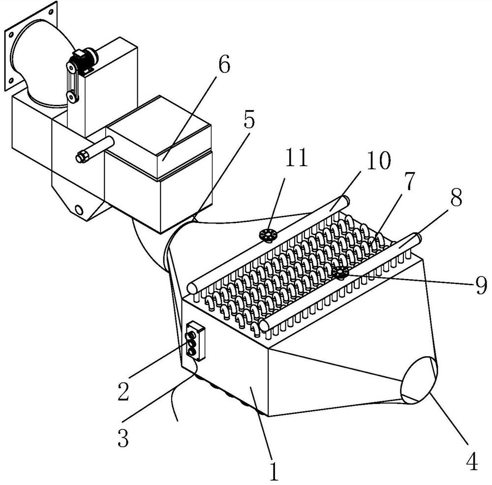
[0031] see figure 1 , the present invention provides a waste heat recovery device for a chemical reaction furnace through improvement, including a heat exchange chamber 1, a controller 2 is fixed on the upper left end of the front surface of the heat exchange chamber 1, and a power cord 3 is arranged at the bottom of the controller 2. There is an air outlet 4 on the right side of the heat exchange chamber 1, the middle part on the left side of the heat exchange chamber 1 is an inlet 5, and a heat exchange tube 7 is embedded in the middle part of the heat exchange chamber 1, and the top right end of the heat exchange tube 7 is connected to the water outlet pipe 8. Water outlet 9 is fixed in the middle part of the top of water outlet pipe 8, water inlet pipe 10 is arranged at the left end of heat exchange pipe 7 top, water inlet 11 is installed in the middle part of the top of water inlet pipe 10, and the left side of inlet 5 is connected with pretreatment device 6.

[0032] see...

Embodiment 2

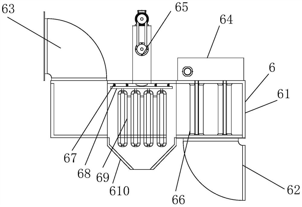
[0037] The present invention provides a waste heat recovery device for a chemical reaction furnace through improvement. A sealing cover is provided on the back of the casing 61, and the sealing cover is bolted to the casing 61, which is convenient for the user to inspect and maintain the inside of the casing 61; The inner wall of 61 is smooth, which reduces the adhesion of impurities and facilitates cleaning; the left side of the inlet 5 and the outlet pipe 62 are fixed by six sets of bolts, and a rubber layer is attached to the connection position of the two to prevent leakage; the guide seat 6510 There is a sliding groove in the middle, and the sliding groove is movably embedded by the pressing piece 658, which effectively guides the movement of the pressing piece 658 and has good stability.

[0038] The present invention provides a waste heat recovery device for a chemical reaction furnace through improvement, and its working principle is as follows;

[0039] First, when th...


PUM


Abstract

The invention discloses a waste heat recovery device for a chemical reaction furnace. The waste heat recovery device comprises a heat exchange bin, a controller, a power line, an air outlet, an inlet,a pretreatment device, a heat exchange pipe, a water outlet pipe, a water outlet, a water inlet pipe and a water inlet. An inlet in the left end of a heat exchange bin is connected with a pretreatment device; the pretreatment device can receive flue gas exhausted from the chemical reaction furnace, a condensation pipe in the pretreatment device condenses water in the flue gas, excessive water vapor entering the heat exchange bin is reduced, a filter screen is installed at the right end of the pretreatment device to effectively block impurities, and excessive impurities in the heat exchange bin are prevented from remaining. The cleaning mechanism is installed at the right end of the top of the pretreatment device, the independent air cylinder is installed in the cleaning mechanism and drives the transmission mechanism to move so that the scraper at the lower end scrapes off impurities attached to the filter screen in a reciprocating mode, the cleaning efficiency is improved, and manualdismounting for cleaning is not needed.

Description

technical field [0001] The invention relates to the related field of waste heat recovery devices, in particular to a waste heat recovery device for chemical reaction furnaces. Background technique [0002] A chemical reaction refers to the process in which molecules are broken into atoms, and atoms are rearranged and combined to form new molecules. New molecules require a special chemical reaction furnace for production and processing in chemical production, and a special waste heat recovery device is required to efficiently recover waste heat during the working process of the chemical reaction furnace. [0003] During the actual use of the waste heat recovery device of the chemical reaction furnace, because there is a large amount of water vapor and some impurities in the flue gas discharged from the chemical reaction furnace, directly entering the heat exchange chamber for heat exchange will easily lead to residual impurities and residual waste at the bottom of the heat ex...

Claims


Application Information

Patent Timeline
Patent Type & Authority Applications(China)
IPC IPC(8): B01D53/00B01D46/12B01D46/00B01D5/00F27D17/00
CPCB01D53/002B01D46/12F27D17/008F27D17/004B01D5/0072B01D5/0039B01D5/0003B01D2258/0283B01D46/681Y02P10/25Y02P70/10
Inventor 钟良华
Owner 惠安畅悦工业产品设计有限公司
Why Eureka
Try Eureka