Self-locking type drill chuck

A drill chuck and self-locking technology, applied in the field of self-locking drill chucks, can solve the problems of complex process, weakened anti-loosening, and the processing technology of the connection relationship between the nut and the nut sleeve is not disclosed.

Pending Publication Date: 2020-10-27
ZHEJIANG CHAOLI MECHANICAL TOOLS
View PDF1 Cites 2 Cited by
  • Summary
  • Abstract
  • Description
  • Claims
  • Application Information

AI Technical Summary

Problems solved by technology

However, first, the effect of keeping the drill chuck open and closed for a long time under the action of the reaction force so that the drilling tool does not loosen still cannot satisfy the user; There will be axial (axial bending, abnormal deformation) and radial (normal deformation) deformation at the same time, such as figure 2 As shown in: F3 and F4 are the directions of axial force, and F5 is the direction of radial force, which will cause the shrapnel to be easily damaged and the effect of preventing loosening will also be weakened
Third, the above-mentioned technical solution discloses a nut, and the key is arranged on the nut. If the key and the nut are integrally formed, the machining process must cut a large amount of iron filings to be processed into an integrated key and nut. The cost is high and the process is complicated. Although its embodiment discloses a nut and a nut sleeve, and the key is located on the nut sleeve, the connection relationship between the nut and the nut sleeve and the processing technology for setting the key of the nut sleeve are not disclosed, and the processing technology of this technology is complicated

Method used


Image

  • Self-locking type drill chuck
  • Self-locking type drill chuck
  • Self-locking type drill chuck

Examples


Embodiment 1

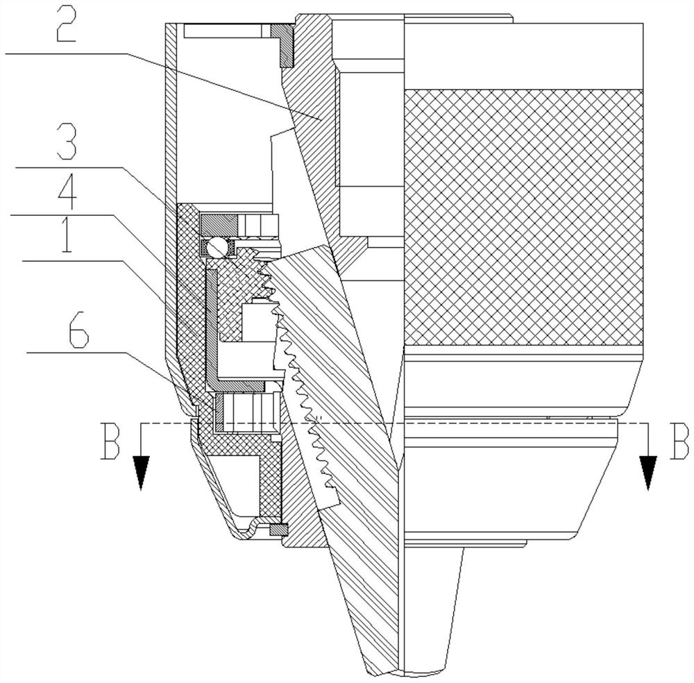
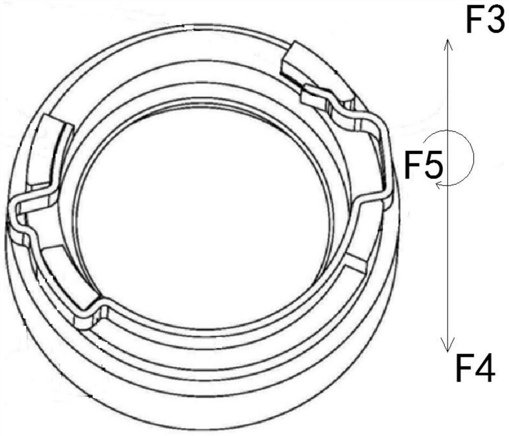
[0033] Such as figure 1 , figure 2 , image 3 , Figure 4 , Image 6 , Figure 7 Shown: a self-locking drill chuck, including a rotating sleeve 1, a drill body 2, a nut 3, and a self-locking structure. The self-locking structure includes teeth 5 and shrapnel 6. The teeth 5 are on the drill body 2. The shrapnel 6 is located on the periphery of the tooth 5 and rotates synchronously with the nut 3. The first end (one end) of the shrapnel 6 is used as a lock end 61 matched with the tooth 5, and a pin is arranged near the second end 65 (the other end). The positioning protrusion 62, the rotating sleeve 1 has a cam structure that controls the locking end 61 of the elastic piece 6, and the rotating sleeve 1 also has a first part that is connected to the elastic piece 6 in the self-locking state and connected to the elastic piece in the non-self-locking state. 6 connected to the second part, the elastic piece 6 is provided with a lock end protrusion 63 that cooperates with the c...

Embodiment 2

[0047] In the above-mentioned embodiment, the rotating sleeve 1 and the housing 101 are separated, and can rotate together through clamping. Of course, as figure 1 , Figure 8 with Figure 9 As shown: the rotating sleeve 1, the shell 101 and the decorative cap 102 can also be integrally formed.

Embodiment 3

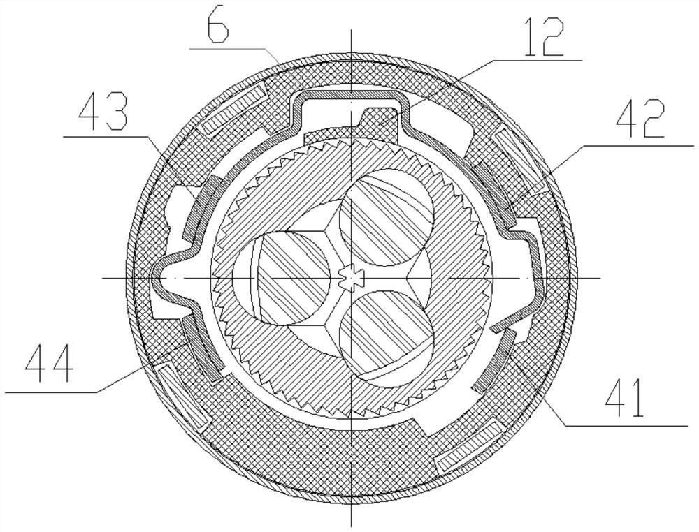
[0049] In the above embodiment, the positioning protrusion and the locking end protrusion are respectively limited between the first key and the second key, between the third key and the fourth key, of course, as figure 2 with Figure 12 Shown: the shrapnel can be inserted between the first key and the second key or between the third key and the fourth key.


PUM


Abstract

The invention discloses a self-locking type drill chuck, belongs to the field of drill chucks, and particularly relates to a self-locking type drill chuck. A nut sleeve is in interference fit with theoutside of a nut, a plurality of keys are arranged on the nut sleeve along the circumferential direction, an elastic sheet is limited among the keys of the nut sleeve through self elasticity to be assembled on the nut, and a supporting protrusion which is arranged between a positioning protrusion and a locking end protrusion and is recessed inwards is arranged on the elastic sheet; and a rotary sleeve is provided with a hollow groove and a supporting convex key which are matched with the supporting protrusion when a non-self-locking state and a self-locking state are mutually switched, in theself-locking state, the supporting convex key abuts against the supporting protrusion of the elastic sheet, and the supporting force is generated on the elastic sheet. The self-locking type drill chuck is simple in structure and high in practicability.

Description

technical field [0001] The invention belongs to the technical field of drill chucks, in particular to a self-locking drill chuck. Background technique [0002] In the prior art, the drill chuck is equipped with a drill body, jaws, nuts, bearings, gaskets, rotating sleeves, and rear sleeves. By rotating the nut, the jaws are driven to move forward or backward to make the chuck clamp Tighten or loosen drilling tools. The self-locking structure in the drill chuck is a structure that prevents the drill from being loosened by the reaction force it receives when the drill chuck is in operation. teeth to match. For the self-locking drill chuck, in order to prevent it from exiting the self-locking state due to inertia, the corresponding connection structure will be set up, but the setting of these structures will cause cumbersome installation steps of the drill chuck and complicated connection structure, which is not conducive to the drill chuck cost control. [0003] For exampl...

Claims


Application Information

Patent Timeline
IPC IPC(8): B23B51/12B23B31/12
CPCB23B31/123B23B51/123
Inventor 王乾赵强
Owner ZHEJIANG CHAOLI MECHANICAL TOOLS
Why Eureka
Try Eureka