Eureka AIR delivers breakthrough ideas for toughest innovation challenges, trusted by R&D personnel around the world.

Steel pipe cutting device for rotating shaft production

A technology of cutting device and steel pipe, applied in the direction of pipe shearing device, shearing device, accessory device of shearing machine, etc., can solve the problems of inability to realize the angle adjustment of the cutting blade, difficulty in moving, etc.

Inactive Publication Date: 2020-10-27
惠州市福昌盛五金制品有限公司
View PDF6 Cites 2 Cited by
  • Summary
  • Abstract
  • Description
  • Claims
  • Application Information

AI Technical Summary

Problems solved by technology

[0004] The invention proposes a steel pipe cutting device for rotating shaft production, which solves the problems that the existing steel pipe cutting device is more difficult to move than the larger steel pipe during the cutting process, and cannot realize the angle adjustment of the cutting piece and the collection of waste

Method used


Image

  • Steel pipe cutting device for rotating shaft production
  • Steel pipe cutting device for rotating shaft production
  • Steel pipe cutting device for rotating shaft production

Examples


Embodiment Construction

[0021] The following will clearly and completely describe the technical solutions in the embodiments of the present invention with reference to the accompanying drawings in the embodiments of the present invention. Obviously, the described embodiments are only some, not all, embodiments of the present invention.

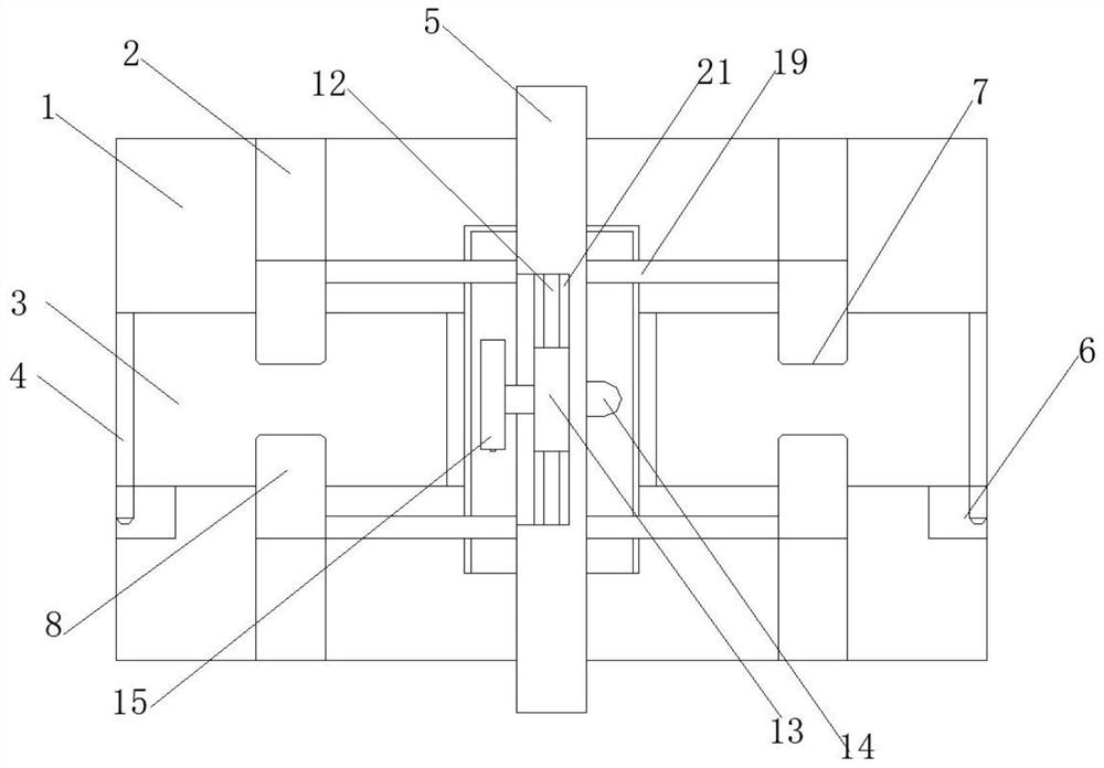
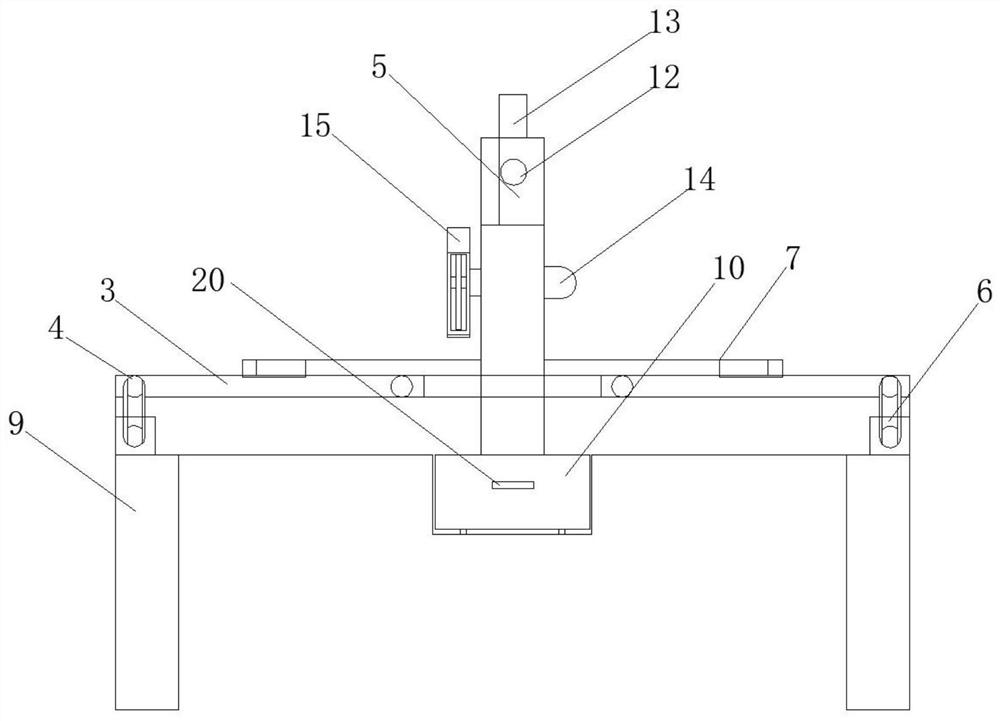
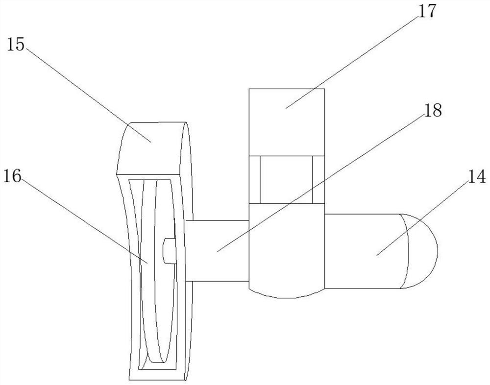
[0022] refer to Figure 1-4 , a steel pipe cutting device for rotating shaft production, comprising a workbench 1, support legs 9 are fixedly installed at the four corners of the bottom end of the workbench 1, and two sets of sliding block movement grooves 2 are opened on the upper surface of the workbench 1, And the two groups of slider movement grooves 2 are symmetrically distributed with respect to the midline of the workbench 1 in the length direction, and a slider 8 is slidably installed in the slider movement groove 2, and is located between the two sliders 8 on the same side. Fixedly connected with connecting rods 19, the first cylinder 11 is fixedly installed...


PUM


Abstract

The invention discloses a steel pipe cutting device for rotating shaft production, and relates to the field of rotating shaft production. The steel pipe cutting device aims at solving the problems that an existing steel pipe cutting device cannot move a steel pipe with a large size in the cutting process, and the angle of a cutting blade cannot be adjusted. According to the scheme, the steel pipecutting device comprises a workbench, wherein supporting legs are fixedly installed at the four corners of the bottom end of the workbench; two sets of sliding block moving grooves are formed in the upper surface of the workbench; the two sets of sliding block moving grooves are symmetrically distributed relative to the center line of the length direction of the workbench; sliding blocks are installed in the sliding block moving grooves in a sliding mode; and a connecting rod is fixedly connected between the two sliding blocks positioned on the same side. The steel pipe cutting device is novelin structure, the stability of the steel pipe is guaranteed in the cutting process of the steel pipe, the workload of workers is reduced to a certain extent by utilizing a conveying belt, and dust pollution in the air is reduced to a certain extent by collecting waste in the cutting process.

Description

technical field [0001] The invention relates to the field of shaft production, in particular to a steel pipe cutting device for shaft production. Background technique [0002] With the continuous development of the times, the level of science and technology has gradually improved. At the same time, in the field of science and technology, people have higher and higher requirements for the devices used for the production of rotating shafts, and the expectations for steel pipe cutting devices are also increasing. [0003] According to the analysis of similar cutting devices existing in the market, we know that they are basically divided into two types, namely, larger cutting devices and smaller cutting devices, and the larger cutting devices occupy a larger area , and the flexibility is not high, and the smaller cutting device is more convenient to use, but has fewer functions and is unstable in fixing the steel pipe. Therefore, in order to solve such problems, we propose a rot...

Claims


Application Information

Patent Timeline
IPC IPC(8): B23D21/00B23D33/02B23Q11/00
CPCB23D21/00B23D33/02B23Q11/0042
Inventor 李勇文梁仲鹏蒋丹军巫伟军魏骁杰
Owner 惠州市福昌盛五金制品有限公司
Why Eureka
Eureka Blog
Learn More