
Axial cutting device for rock core sampling tube without damaging sample

A cutting device and core sampling technology, which is applied to the attachment device of sawing machine, sawing machine device, metal sawing equipment, etc., can solve the problems of core sample crushing, unfavorable core sample composition distribution, detection, etc.

Inactive Publication Date: 2020-10-27
GUANGZHOU MARINE GEOLOGICAL SURVEY
View PDF11 Cites 1 Cited by
  • Summary
  • Abstract
  • Description
  • Claims
  • Application Information

AI Technical Summary

Problems solved by technology

[0002] In geological survey, it is necessary to sample and test geological rocks and other substances. The current core sampling is to drill into the core through a steel sampling tube through drilling equipment, so that the inside of the sampling tube is cut and filled with core samples, and then the sampling tube is cut out. For core samples, most of the current cutting methods directly cut the sampling tube into two halves by a cutting machine. This kind of cutting often cuts the core samples in half, which easily leads to the crushing of the core samples, which is not conducive to the detection of the composition distribution of the core samples. , so we propose a non-destructive sample core sampling tube axial cutting device to solve the above problems

Method used


Image

  • Axial cutting device for rock core sampling tube without damaging sample
  • Axial cutting device for rock core sampling tube without damaging sample
  • Axial cutting device for rock core sampling tube without damaging sample

Examples


Embodiment Construction

[0030] The following will clearly and completely describe the technical solutions in the embodiments of the present invention with reference to the accompanying drawings in the embodiments of the present invention. Obviously, the described embodiments are only some, not all, embodiments of the present invention. Based on the embodiments of the present invention, all other embodiments obtained by persons of ordinary skill in the art without making creative efforts belong to the protection scope of the present invention.

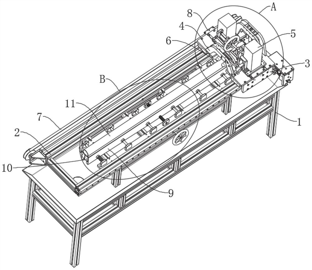
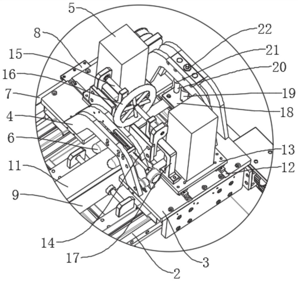
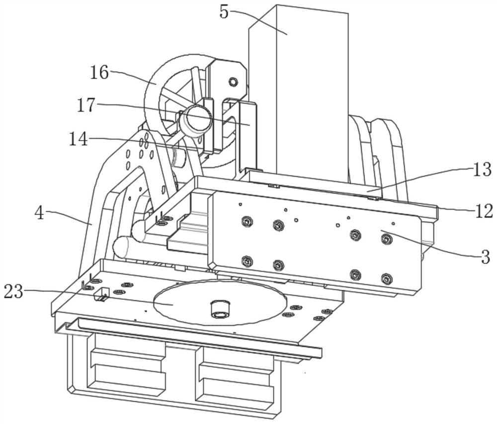
[0031] see Figure 1-Figure 5 , a core sampling tube 11 axial cutting device without damage to samples, comprising a base frame 1 and a support device arranged on the base frame 1, a guide device, a driving device, a cutting device, a first limit fixing device, a second limit position fixing device and the third limit fixing device, the support device is used to support and store the sampling tube 11 and the sample in the sampling tube 11, the driving device i...


PUM


Abstract

The invention discloses an axial cutting device for a rock core sampling tube without damaging a sample. The axial cutting device comprises a base frame, a supporting device, a guiding device, a driving device, a cutting device, first limiting fixing devices, second limiting fixing devices and a third limiting fixing device, wherein the supporting device, the guiding device, the driving device, the cutting device, the first limiting fixing devices, the second limiting fixing devices and the third limiting fixing device are arranged on the base frame; the supporting device is used for supporting the sampling tube; the driving device is connected with the cutting device and is used for driving the cutting device to move; the cutting device stretches across two sides of the supporting device;the first limiting fixing devices are arranged along the axial direction of the guiding device and are used for limiting and fixing the movement of the sampling tube along the radial direction; the second limiting fixing devices are arranged on two sections of the guiding device and are used for limiting and fixing the movement of the sampling tube along the axial direction; and the third limiting fixing device is arranged on the cutting device, moves along with the cutting device and is used for limiting and fixing the movement of the sampling tube along the vertical direction. The axial cutting device disclosed by the invention can be used for quickly and effectively cutting off tube walls on two sides of the sampling tube without damaging the sample, so as to obtain a complete rock core sample.

Description

technical field [0001] The invention relates to the technical field of sample cutting devices, in particular to an axial cutting device for a rock core sampling tube without damaging samples. Background technique [0002] In geological survey, it is necessary to sample and test geological rocks and other substances. The current core sampling is to drill into the core through a steel sampling tube through drilling equipment, so that the inside of the sampling tube is cut and filled with core samples, and then the sampling tube is cut out. For core samples, most of the current cutting methods directly cut the sampling tube into two halves by a cutting machine. This kind of cutting often cuts the core samples in half, which easily leads to the crushing of the core samples, which is not conducive to the detection of the composition distribution of the core samples. Therefore, we propose a non-destructive sample core sampling tube axial cutting device to solve the above problems....

Claims


Application Information

Patent Timeline
IPC IPC(8): B23D45/12B23D47/02B23D47/04B23D47/12B23D59/00B23Q11/00
CPCB23D45/12B23D47/02B23D47/04B23D47/12B23D59/00B23Q11/0042
Inventor 耿雪樵李力李柯良罗贤虎莫建田烈余王世栋杨楠任旭光林康廖天保闫卫召罗红波
Owner GUANGZHOU MARINE GEOLOGICAL SURVEY
Learn More