
Laser cutting jig circulating mechanism

A technology of laser cutting and circulation mechanism, which is applied in the direction of laser welding equipment, manufacturing tools, welding equipment, etc., and can solve the problem of taking up time

Inactive Publication Date: 2020-10-27
SHENZHEN MICROMACH TECH CO LTD
View PDF16 Cites 0 Cited by
  • Summary
  • Abstract
  • Description
  • Claims
  • Application Information

AI Technical Summary

Problems solved by technology

The main problem of the existing jigs is: one processing can only cut the products in a single jig, and the processing needs to be suspended every time the material is loaded and unloaded, which takes up a lot of time

Method used


Image

  • Laser cutting jig circulating mechanism

Examples


Embodiment Construction

[0017] Embodiments of the present invention will be described in detail below in conjunction with examples, but those skilled in the art will understand that the following examples are only for illustrating the present invention, and should not be considered as limiting the scope of the present invention. Those who do not indicate the specific conditions in the examples are carried out according to the conventional conditions or the conditions suggested by the manufacturer.

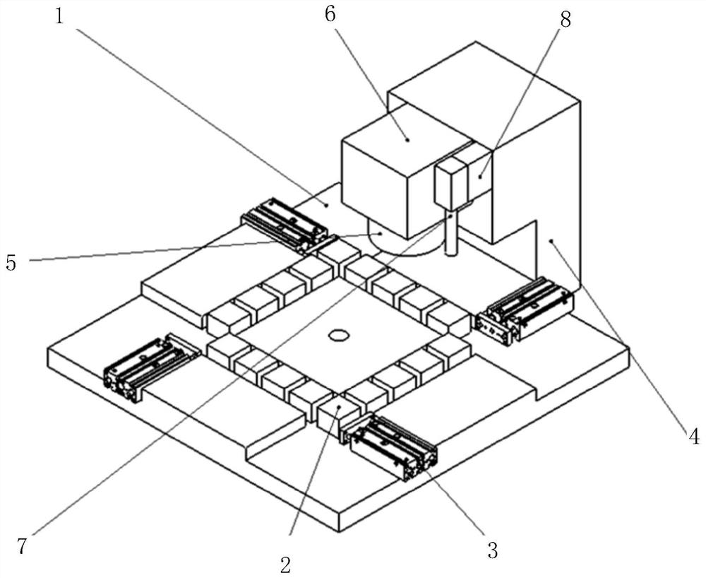
[0018] see figure 1 , a laser cutting jig circulation mechanism in one embodiment, comprising: a roughly square platform 1, a plurality of tracks are provided on the platform 1, and the plurality of tracks are arranged in sequence, specifically, there are 4 tracks, and the 4 tracks are arranged in sequence to form A square; several jigs 2 are placed along the track of the platform 1, and the jig 2 can move along the track; one end of each track is provided with a driving mechanism 3 for driving the jig 2 ...


PUM


Abstract

The invention relates to a laser cutting jig circulating mechanism. The laser cutting jig circulating mechanism comprises a platform, a plurality of jigs and driving mechanisms; a plurality of guide rails are arranged on the platform and are in square shape; the plurality of jigs can move along the rails; the driving mechanisms are correspondingly arranged at one ends of the rails and are used fordriving the jigs to move along the rails; and during each time of driving, the two diagonal driving mechanisms drive the jigs on the two rails to move by a unit distance at the same time, and then the other two diagonal driving mechanisms are switched to be started at the same time, so that the jigs on the other two rails are driven to move by the unit distance, and feeding and discharging or material switching is achieved through the cyclic movement. The laser cutting jig circulating mechanism is high in efficiency and low in cost.

Description

technical field [0001] The invention relates to the technical field of laser cutting, in particular to a laser cutting jig circulation mechanism. Background technique [0002] In the field of laser cutting, various types of adsorption fixtures are indispensable. Commonly used jigs are similar in structure, fixed on the X / Y axis, and move together with the axis, and achieve the purpose of precision cutting through the coordinated linear motion of the X and Y axes. In order to improve processing efficiency, many companies have developed laser cutting equipment with double fixtures or even four fixture platforms, but the efficiency has also increased a lot at the same time. The main problem of the existing jigs is that only one product in a single jig can be cut in one process, and the processing needs to be suspended every time the material is loaded and unloaded, which takes up a lot of time. Contents of the invention [0003] The technical problem mainly solved by the pr...

Claims


Application Information

Patent Timeline
Patent Type & Authority Applications(China)
IPC IPC(8): B23K26/38B23K26/082B23K26/064B23K26/70
CPCB23K26/38B23K26/064B23K26/082B23K26/702
Inventor 向阳蔡有汉林小波乔磊
Owner SHENZHEN MICROMACH TECH CO LTD
Features
  • Generate Ideas
  • Intellectual Property
  • Life Sciences
  • Materials
  • Tech Scout
  • Unparalleled Data Quality
  • Higher Quality Content
  • 60% Fewer Hallucinations
Learn More