Clamping device for slitting of computer display card cooling fins

A technology of clamping device and heat sink, which is applied in the direction of workpiece clamping device, manufacturing tools, etc., can solve the problems that the clamping stability cannot be guaranteed, the clamping device is not equipped with an ejector device, and the work efficiency is affected

Active Publication Date: 2020-10-27
GUIZHOU INST OF TECH
View PDF5 Cites 2 Cited by
  • Summary
  • Abstract
  • Description
  • Claims
  • Application Information

AI Technical Summary

Problems solved by technology

[0004] 1. Due to the relatively simple structure of the existing clamping device, it is easy to vibrate when cutting the heat sink, which affects the quality of the slit heat sink. In addition, the simple clamping cannot guarantee the stability of the clamping ;
[0005] 2. The existing clamping device is not equipped with an ejector device, which is inconvenient for unloading and affects work efficiency after the slitting is completed;
[0006] 3. As mentioned above, most of the existing heat sinks use copper bases and aluminum fins to cooperate, and the heat dissipation effect needs to be improved; therefore, how to improve the heat dissipation effect and improve the processing efficiency in a limited space has become the focus of attention

Method used


Image

  • Clamping device for slitting of computer display card cooling fins
  • Clamping device for slitting of computer display card cooling fins
  • Clamping device for slitting of computer display card cooling fins

Examples


Embodiment Construction

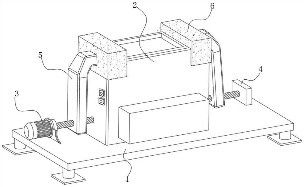
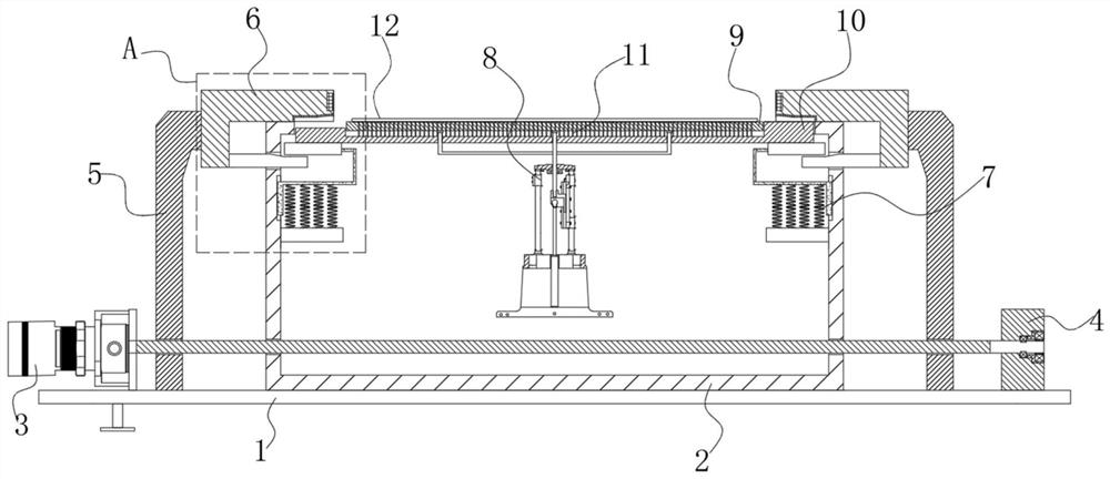
[0032] see Figure 1~4 , in an embodiment of the present invention, a clamping device for cutting heat sinks of computer graphics cards, which includes a base 1, a mounting seat 2, a moving arm 5, a locking assembly 6, a supporting assembly 7 and a processing table 10, wherein the The mounting seat 2 is fixed on the base 1, and the mounting seat 2 is a cavity structure, and an opening is provided on the top thereof for the processing table 10 to move up and down along the opening;

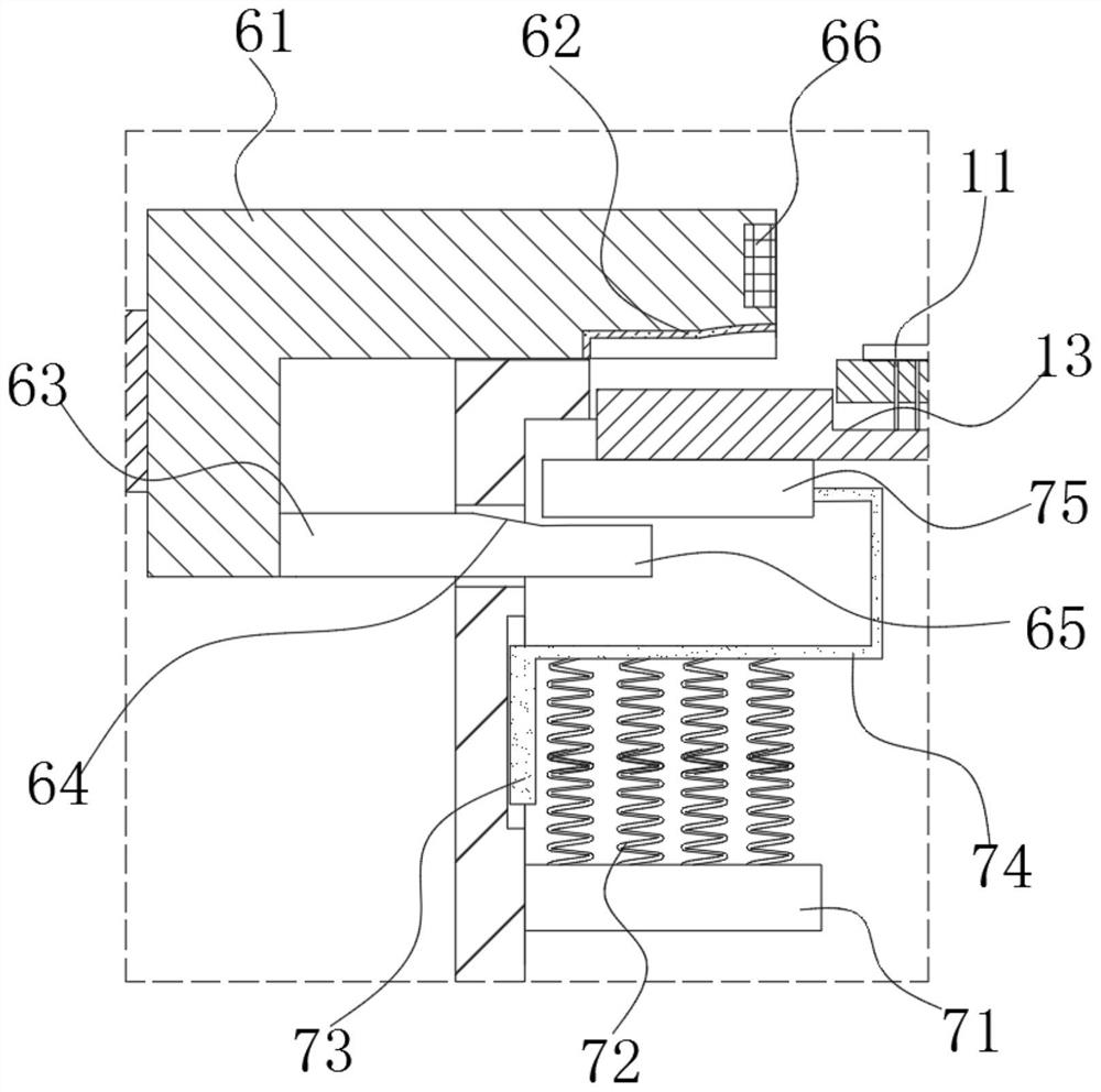
[0033] Wherein, the middle part of the processing table 10 is provided with an accommodating groove 13, and the bottom of the accommodating groove 13 is uniformly arranged with a vertically placed pit-shaped needle 11, and the top of the pit-shaped needle 11 is spherical, And it is used to place the heat sink 12 to be cut;

[0034] Both sides of the mounting base 2 are symmetrically provided with moving arms 5 capable of horizontal displacement, and each of the moving arms 5 is provided with a loc...


PUM


Abstract

The invention discloses a clamping device for slitting of computer display card cooling fins. The clamping device comprises a base, a mounting seat, movable arms, locking assemblies, top bracing assemblies and a machining table. The mounting seat is fixed to the base, the mounting seat is of a hollow cavity, an opening is formed in the top of the mounting seat, and the mounting seat is used for enabling the machining table to move up and down along the position of the opening of the mounting seat. A containing groove is formed in the middle of the machining table, vertically-put pit molding needles are evenly distributed at the bottom of the containing groove, and the upper faces of the pit molding needles are in round ball shapes and are used for containing the to-be-slit cooling fins. The movable arms capable of moving horizontally are symmetrically arranged on the two sides of the mounting seat, one locking assembly is arranged on each movable arm, when the to-be-slit cooling fins are clamped and locked, the locking assemblies can lock the to-be-slit cooling fins in the pit molding needles while ejecting the machining table upwards through the top bracing assemblies, and therefore pits in the to-be-slit cooling fins are molded.

Description

technical field [0001] The invention relates to the technical field of clamping devices, in particular to a clamping device for cutting heat sinks of computer graphics cards. Background technique [0002] As a heat conduction medium for the GPU, the heat sink of the graphics card can increase the heat exchange area of ​​the chip to achieve the purpose of rapid heat dissipation. Usually, this type of heat sink uses a copper base and aluminum fins to match, and the copper base It is in contact with the chip, and multiple sets of fins are welded on the copper base to maximize the heat dissipation area. Before welding, the heat sink needs to be cut into the required size, so a clamping device is needed for assistance processing. [0003] After investigation and analysis, the existing clamping device and the heat dissipation of aluminum fins have the following problems: [0004] 1. Due to the relatively simple structure of the existing clamping device, it is easy to vibrate whe...

Claims


Application Information

Patent Timeline
Patent Type & Authority Applications(China)
IPC IPC(8): B25B11/00
CPCB25B11/00
Inventor 王喜宾丁阿丹杨剑锋郭晟南
Owner GUIZHOU INST OF TECH
Why Eureka
Try Eureka