
Control method, electric transmission system and electric locomotive

A technology of electric locomotive and control method, which is applied in the field of control and can solve the problems of reducing extra loss of permanent magnet synchronous motor and increasing work efficiency

Active Publication Date: 2020-10-27
CRRC YONGJI ELECTRIC CO LTD
View PDF8 Cites 0 Cited by
  • Summary
  • Abstract
  • Description
  • Claims
  • Application Information

AI Technical Summary

Problems solved by technology

[0004] The present application provides a control method, an electric transmission system and an electric locomotive, which are used to solve the technical problems that the existing method of suppressing high back EMF will bring additional loss, reduce the working efficiency of the permanent magnet synchronous motor and increase the system cost of the transmission system

Method used


Image

  • Control method, electric transmission system and electric locomotive
  • Control method, electric transmission system and electric locomotive
  • Control method, electric transmission system and electric locomotive

Examples


Embodiment Construction

[0045] Reference will now be made in detail to the exemplary embodiments, examples of which are illustrated in the accompanying drawings. When the following description refers to the accompanying drawings, the same numerals in different drawings refer to the same or similar elements unless otherwise indicated. The implementations described in the following exemplary embodiments do not represent all implementations consistent with this application. Rather, they are merely examples of methods and apparatus consistent with aspects of the present application as recited in the appended claims.

[0046]The terms "first", "second", "third", "fourth", etc. (if any) in the description and claims of this application and the above drawings are used to distinguish similar objects and not necessarily Describe a specific order or sequence. It is to be understood that the data so used are interchangeable under appropriate circumstances such that the embodiments of the application described...


PUM


Abstract

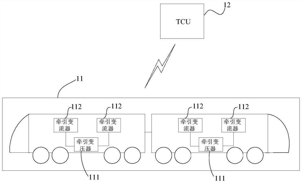
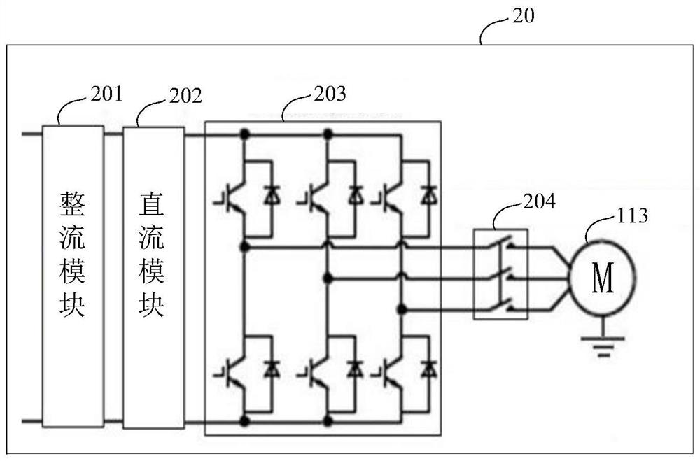
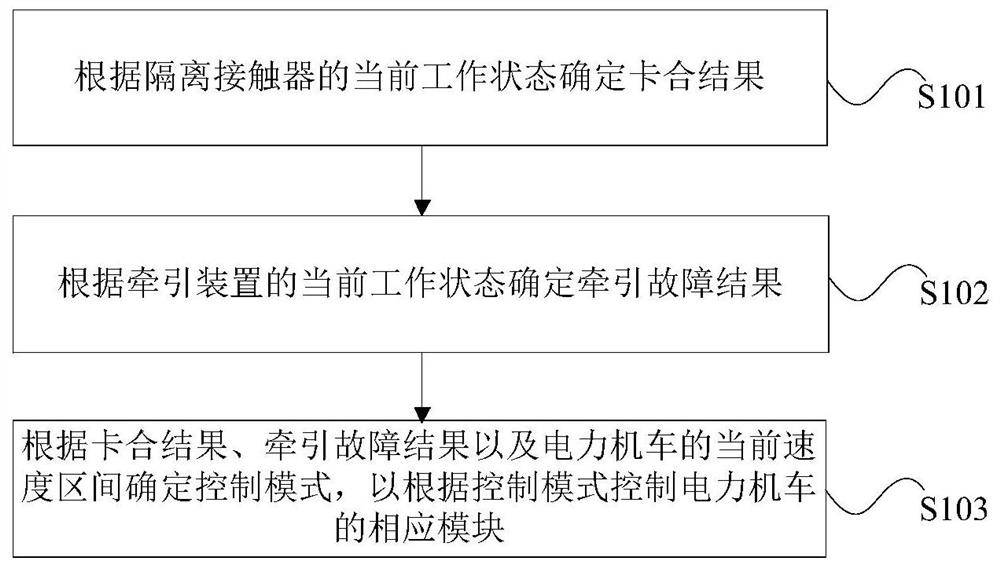
The invention provides a control method, an electric transmission system and an electric locomotive. The control method provided by the invention is applied to an electric transmission system of the electric locomotive, each traction converter of the electric transmission system comprises at least two groups of traction devices, and each group of traction devices drives a permanent magnet synchronous motor through a rectification module, a direct current module, an inversion module and an isolation contactor which are electrically connected in sequence. Firstly, a clamping result is determinedaccording to the current working state of the isolation contactor; a traction fault result is determined according to the current working state of the traction device; a control mode is determined jointly by combining the current speed interval of the electric locomotive; corresponding modules of the electric locomotive are controlled according to the control mode; therefore, the influence of high counter electromotive force on the electric transmission system is effectively suppressed based on various actual working conditions of the electric locomotive and the electric transmission system thereof, extra system loss is not caused, frequent control of an isolation contactor is avoided, the service life of the isolation contactor is prolonged, and the safety and reliability of the system are improved.

Description

technical field [0001] The present application relates to the technical field of control, in particular to a control method, an electric drive system and an electric locomotive. Background technique [0002] Permanent magnet synchronous motors have been widely used in rail transit traction drive systems due to their excellent characteristics such as high power density, large output torque at low speeds, high efficiency, and easy maintenance. However, in actual working conditions, there is often a situation that the power supply to the permanent magnet synchronous motor is stopped, but it is still rotating, for example, when the permanent magnet synchronous motor is dragged, at this time, the permanent magnet on the motor rotor still generates The rotor rotates the magnetic field, and the induced electromotive force of the magnetic field in the three-phase winding of the stator is called the counter electromotive force of the permanent magnet synchronous motor. When the perm...

Claims


Application Information

Patent Timeline
Patent Type & Authority Applications(China)
IPC IPC(8): B60L3/00B61C3/00B60L15/20H02P6/00H02P6/04
CPCB60L3/0061B60L15/20B60L2200/26B61C3/00H02P6/00H02P6/04Y02T10/64Y02T10/72
Inventor 詹哲军王彬贺志学张瑞峰杨高兴路瑶王力苏鹏程
Owner CRRC YONGJI ELECTRIC CO LTD
Learn More