Hydraulic oil cylinder assembly

A hydraulic cylinder and assembly technology, which is applied in the direction of fluid pressure actuating devices, etc., can solve problems such as piston damage, reduced service life of hydraulic cylinders, unfavorable installation of end caps, etc.

Inactive Publication Date: 2020-10-27
胡单
View PDF12 Cites 4 Cited by
  • Summary
  • Abstract
  • Description
  • Claims
  • Application Information

AI Technical Summary

Problems solved by technology

[0003] The current hydraulic cylinder is a hydraulic component that uses the pressurization of hydraulic oil to realize the movement of the piston rod. However, for the hydraulic cylinder assembly, the collision between the piston and the pipe body may occur due to the excessive speed of the hydraulic cylinder during movement. The problem of piston damage is not conducive to the long-term use of th

Method used


Image

  • Hydraulic oil cylinder assembly
  • Hydraulic oil cylinder assembly
  • Hydraulic oil cylinder assembly

Examples


Embodiment Construction

[0024] In order to make the purpose, features and advantages of the present invention more obvious and understandable, the technical solutions in the embodiments of the present invention will be clearly and completely described below with reference to the accompanying drawings in the embodiments of the present invention. Obviously, the following The described embodiments are only some, but not all, embodiments of the present invention. Based on the embodiments of the present invention, all other embodiments obtained by those of ordinary skill in the art without creative efforts shall fall within the protection scope of the present invention.

[0025] The technical solutions of the present invention are further described below with reference to the accompanying drawings and through specific embodiments.

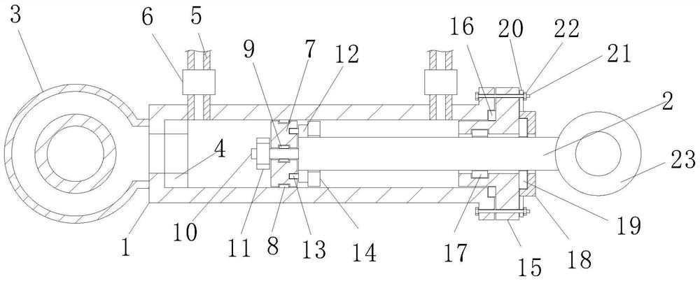
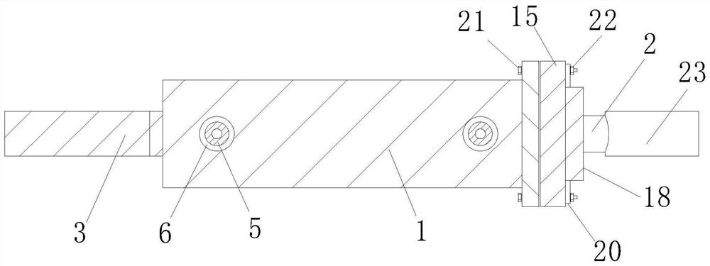
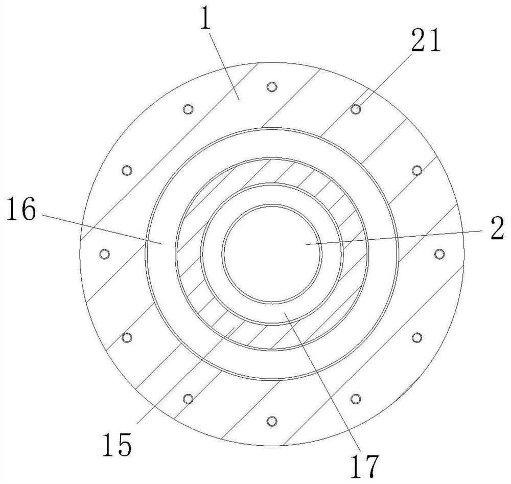
[0026] see Figure 1-4 As shown, a hydraulic oil cylinder assembly includes a piston rod 2 inside a pipe body 1, a buffer mechanism and a mounting mechanism; the buffer mecha...


PUM


Abstract

The invention relates to the technical field of hydraulic oil cylinder application, in particular to a hydraulic oil cylinder assembly. The hydraulic oil cylinder assembly comprises a pipe body, a piston rod, a first connecting pipe, a first cushion, communicating pipes, joints, a piston, a first sealing ring, a second sealing ring, a fixing rod, a first nut, a fixing block, limiting rods, a second cushion, an end cover, a sealing gasket, a third sealing ring, a limiting plate, a dustproof pad, a fixing plate, screw rods, a second nut and a second connecting pipe. The hydraulic oil cylinder assembly is simple in structure and convenient to operate, the buffering capacity is effectively increased during movement of the piston through the design of the cushions, the problem that the piston is damaged due to collision with the pipe body when the piston moves rapidly is avoided, and long-time use of the hydraulic oil cylinder is facilitated; and through the design of the limiting plate, the dustproof pad can be limited and mounted conveniently, dust protection of the connecting position of the piston rod and the end cover is facilitated, dust entering is effectively avoided, and meanwhile fixing of the dustproof pad is facilitated.

Description

technical field [0001] The invention relates to the technical field of hydraulic oil cylinder applications, in particular to a hydraulic oil cylinder assembly. Background technique [0002] Hydraulic cylinder is a hydraulic actuator that converts hydraulic energy into mechanical energy and performs linear reciprocating motion or swinging motion. It has a simple structure and reliable operation. When it is used to realize reciprocating motion, the reduction device can be omitted, and there is no transmission gap. It is stable, so it is widely used in various mechanical hydraulic systems. The output force of the hydraulic cylinder is proportional to the effective area of ​​the piston and the pressure difference on both sides; , buffer device and exhaust device. Buffers and exhausts are application specific, other devices are essential. [0003] The current hydraulic cylinder is a hydraulic component that uses the pressurization of hydraulic oil to realize the movement of the...

Claims


Application Information

Patent Timeline
IPC IPC(8): F15B15/14F15B15/22
CPCF15B15/1423F15B15/1438F15B15/1442F15B15/1433F15B15/1452F15B15/1447F15B15/1461F15B15/149F15B15/226
Inventor 胡单张继
Owner 胡单
Why Eureka
Try Eureka