
Hydraulic joint for hydraulic valve

A technology of hydraulic joints and valves, which is applied in the direction of pipes/pipe joints/pipe fittings, connections with fluid cut-off devices, passing components, etc., which can solve the problems of increasing use costs and general sealing performance of connections, so as to enhance sealing performance and improve The effect of improving connection performance and improving the overall airtightness

Pending Publication Date: 2020-10-27
SHANGHAI SAIMUNO HYDRAULIC PARTS CO LTD
View PDF0 Cites 0 Cited by
  • Summary
  • Abstract
  • Description
  • Claims
  • Application Information

AI Technical Summary

Problems solved by technology

[0003] Existing hydraulic joints for hydraulic valves are usually difficult to satisfy both one-way and two-way circulation according to actual needs when one-way circulation is satisfied, resulting in the need for users to purchase different hydraulic joints according to different needs, thereby increasing the cost of use , and the tightness of the connection between the joint and the device is relatively general

Method used


Image

  • Hydraulic joint for hydraulic valve
  • Hydraulic joint for hydraulic valve
  • Hydraulic joint for hydraulic valve

Examples


Embodiment Construction

[0018] In order to make the object, technical solution and advantages of the present invention clearer, the present invention will be described in detail below in conjunction with the accompanying drawings and specific embodiments. It should be understood that the specific embodiments described here are only used to explain the present invention, not to limit the present invention.

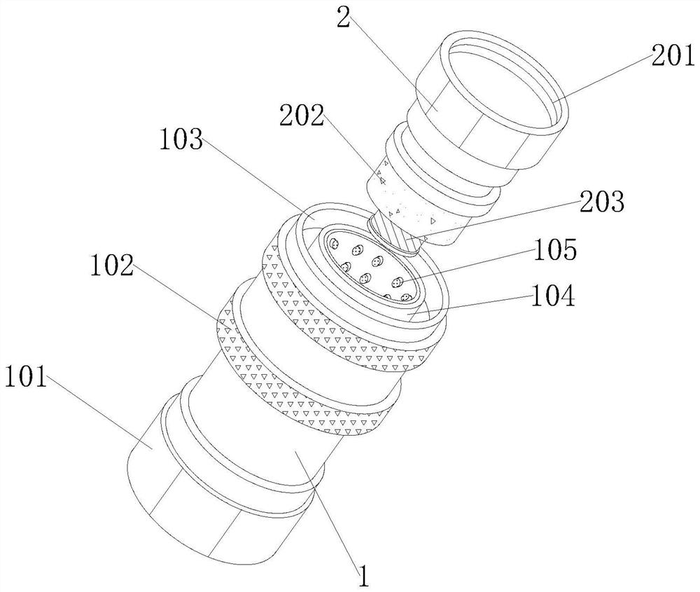
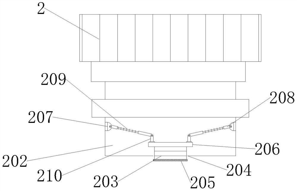
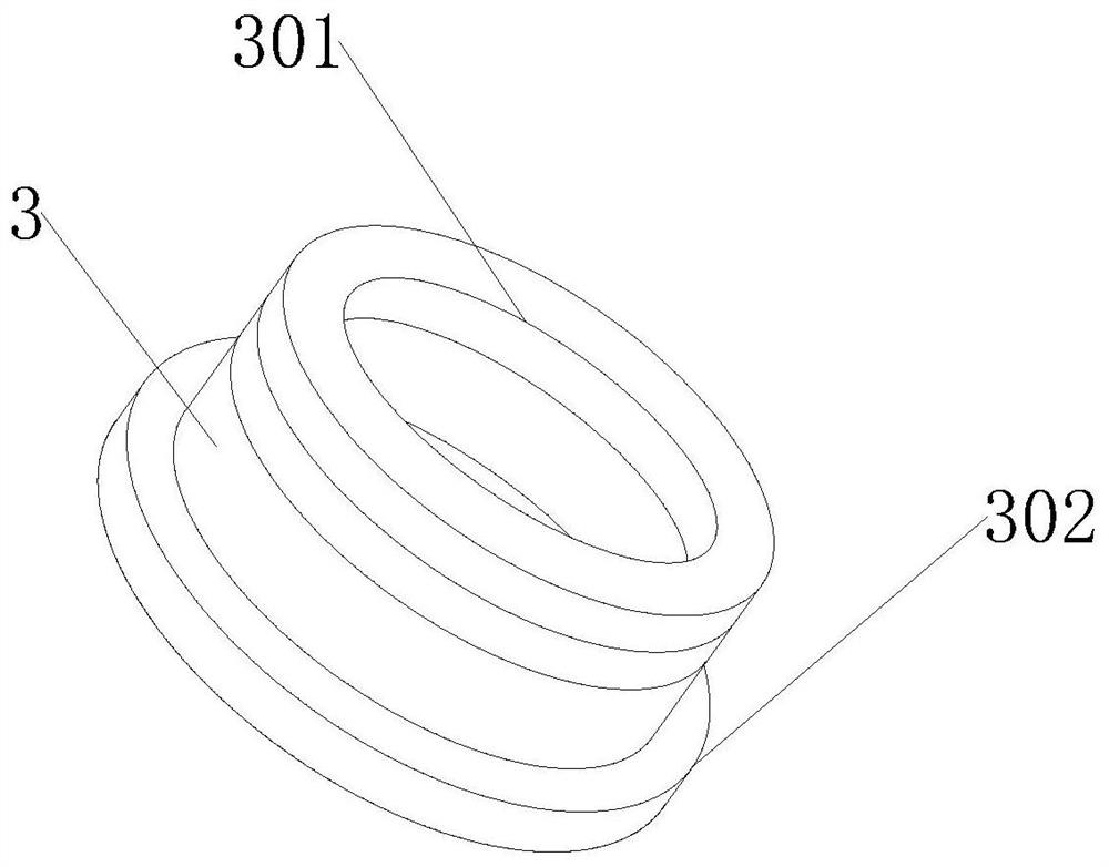
[0019] Such as Figure 1-3 As shown, a hydraulic joint for hydraulic valves, the hydraulic joints for hydraulic valves include:

[0020] The joint pipe body 1, the joint pipe body 1 includes a connecting pipe 2 plugged into its upper end and communicating with it, and the upper surface of the connecting pipe 2 is provided with a threaded groove 201 communicating with it, and the end of the connecting pipe 2 is inserted with a cannula communicating with it 202, and the bottom center of the inner surface of the intubation tube 202 has a jack 204 communicating with it, and a piston tube 203 is embed...


PUM


Abstract

The invention provides a hydraulic joint for a hydraulic valve, and relates to the technical field of hydraulic joints. The hydraulic joint for the hydraulic valve comprises a joint pipe body, whereinthe joint pipe body comprises a connecting pipe which is inserted into the upper end of the joint pipe body and communicates with the joint pipe body; a threaded groove communicating with the connecting pipe is formed in the upper surface of the connecting pipe; an inserting pipe communicating with the connecting pipe is inserted into the tail end of the connecting pipe; an inserting hole communicating with the inserting pipe is formed in the center of the bottom of the inner surface of the inserting pipe; a piston pipe is embedded into the inserting hole; a first rubber ring and a second rubber ring are bonded to the tail end and the top end of the piston pipe correspondingly; connecting blocks are symmetrically welded to the left side and the right side of the inner wall of the inserting pipe; the right ends, far away from the inner wall of the inserting pipe, of the two connecting blocks are rotationally connected with inclined rods through rotating shafts; spring rods are welded to the middle positions of the inclined rods; and the tail ends of the inclined rods are rotationally connected with vertical rods through rotating shafts. The hydraulic joint has the beneficial effects that the single-double-stop circulation requirement of a user is met, and the sealing performance of the joint is improved.

Description

technical field [0001] The invention relates to the technical field of hydraulic joints, in particular to a hydraulic joint used for hydraulic valves. Background technique [0002] Hydraulic pipe joints are formed by connecting different hydraulic components (pumps, delivery lines, reversing valves, globe valves, hydraulic motors, hydraulic cylinders, and some auxiliary components, such as liquid level gauges, thermometers, pressure gauges, etc.) A closed circuit hydraulic system is an accessory that acts as a connection. [0003] Existing hydraulic joints for hydraulic valves are usually difficult to satisfy both one-way and two-way circulation according to actual needs when one-way circulation is satisfied, resulting in the need for users to purchase different hydraulic joints according to different needs, thereby increasing the cost of use , and the connection between the joint and the device is more general. Contents of the invention [0004] The technical problem to...

Claims


Application Information

Patent Timeline
IPC IPC(8): F16L29/02
CPCF16L29/02
Inventor 顾晓明
Owner SHANGHAI SAIMUNO HYDRAULIC PARTS CO LTD
Learn More