Space on-orbit liquid acquiring device for cryogenic propellant

A low-temperature propellant and acquisition device technology, which is applied in the direction of aerospace vehicle propulsion system device, container structure installation device, gas/liquid distribution and storage, etc., can solve the problem of large weight, complex structure, and low-temperature propellant gas-liquid Issues such as separation and full liquid acquisition on-orbit mature application solutions

Active Publication Date: 2020-10-27
XI AN JIAOTONG UNIV
View PDF12 Cites 4 Cited by
  • Summary
  • Abstract
  • Description
  • Claims
  • Application Information

AI Technical Summary

Problems solved by technology

Active management technologies such as inertial type and spin type require continuous consumption of high-cost low-temperature propellants, which are not economical for large-scale systems
The flexible diaphragm storage tank used for normal temperature propellants is no longer suitable for low temperature propellants that are easy to evaporate because they cannot eliminate the gas evaporated on the liquid side
Passive gas-liquid management technologies mainly include trough type, trap type, sponge type, blade plate type, screen channel type, etc. Among them, the trough type gas-liquid management device can be refilled, but it is very sensitive to the direction of acceleration; the reaction of the trap type dev

Method used


Image

  • Space on-orbit liquid acquiring device for cryogenic propellant

Examples


Embodiment Construction

[0020] The technical solutions of the present invention will be further described below in conjunction with the drawings and embodiments.

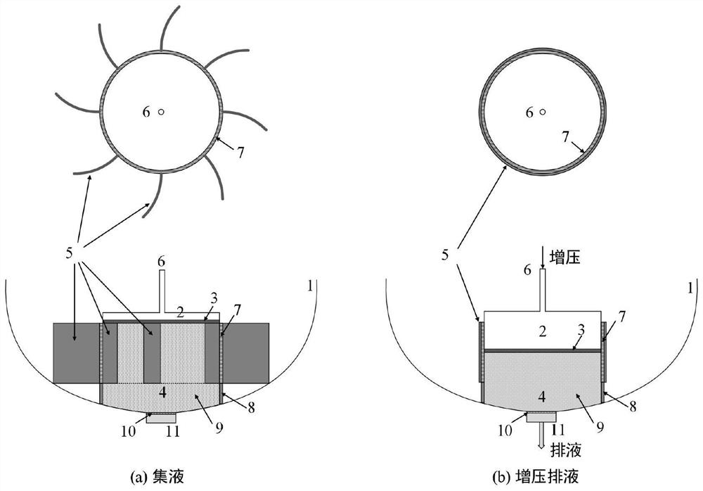
[0021] refer to figure 1 , a low-temperature propellant space on-orbit liquid acquisition device, including a pressurization chamber 2, a liquid collection chamber 4 and a set of movable vane plates 5, the outer container structure of the pressurization chamber 2 and liquid collection chamber 4 is a whole, installed in The bottom of the low-temperature propellant tank 1; the pressurization chamber 2 and the liquid collection chamber 4 are separated into two independent areas by the moving piston 3, and the volume distribution of the pressurization chamber 2 and the liquid collection chamber 4 is determined by the position of the moving piston 3.

[0022] The upper end of the pressurized chamber 2 is provided with a pressurized port 6, which is connected to a pressurized system; the pressurized gas can be a non-condensable gas such as heliu...


PUM

PropertyMeasurementUnit
Apertureaaaaaaaaaa

Abstract

The invention discloses a space on-orbit liquid acquiring device for a cryogenic propellant. The space on-orbit liquid acquiring device comprises a booster cavity, a liquid collecting cavity and one group of movable vane plates, wherein the booster cavity and an outer container structure of the liquid collecting cavity form a whole; the integral structure is arranged at the bottom of a cryogenic propellant storage tank; the booster cavity and the liquid collecting cavity are separated into two separate areas by a movable piston; the upper end of the booster cavity is provided with a boosting port; the boosting port is connected with a boosting system; liquid collecting sponge fills the liquid collecting cavity; the lower end of the liquid collecting cavity is provided with a drain outlet of the cryogenic propellant storage tank; a layer of porous metal screen is arranged between the liquid collecting cavity and the drain outlet; the side wall surfaces of the liquid collecting cavity are divided into two parts; the upper wall surfaces are perforated wall surfaces, and the lower wall surfaces are solid wall surfaces; and the movable vane plates are arranged at the peripheries of theperforated wall surfaces, so that a vane group can completely wrap the perforated wall surfaces when rotating to be attached to the perforated wall surfaces. The space on-orbit liquid acquiring devicefor the cryogenic propellant, disclosed by the invention, realizes effective management for gas-liquid distribution of the space on-orbit cryogenic propellant, so that the liquid acquiring device forthe cryogenic propellant is more stable and reliable and wider in application range of working conditions.

Description

technical field [0001] The invention relates to the technical field of low-temperature propellant space fluid management, in particular to an on-orbit liquid acquisition device for low-temperature propellant space. Background technique [0002] On-orbit ignition of spacecraft engines, on-orbit pressurization and transmission of propellants all require a continuous and stable supply of single-phase liquid propellants. Under ground conditions, the gas-liquid phase can be well stratified by gravity. Under orbital microgravity conditions, the distribution of gas-liquid phases is highly random, and gas-liquid positioning and separation must be realized through gas-liquid management technology. In recent years, low-temperature propellants such as liquid hydrogen and liquid oxygen have been widely used in large-scale launch vehicle systems due to their high specific impulse, high thrust, non-toxic and non-polluting advantages, and are the preferred propellants for future large-sca...

Claims


Application Information

Patent Timeline
IPC IPC(8): F17C1/00F17C7/02F17C13/00B64G1/40
CPCB64G1/402F17C1/00F17C7/02F17C13/00F17C2205/0149F17C2205/03F17C2205/0341F17C2205/0391F17C2221/01F17C2223/0161F17C2225/013F17C2227/01F17C2227/0192F17C2250/0615F17C2250/0689F17C2250/075F17C2270/0194
Inventor 马原厉彦忠王磊谢福寿李剑
Owner XI AN JIAOTONG UNIV
Why Eureka
Try Eureka