A heat pump drying system and method

A technology of heat pump drying and drying system, which is applied in drying cargo handling, drying solid materials, drying gas layout, etc., can solve the problems of unstable moisture content of dried products, small heat exchange area, low drying efficiency, etc. The effect of uniform and efficient, improving COP coefficient and stable product moisture content

Active Publication Date: 2021-10-01
天津乐科节能科技有限公司 +1
View PDF8 Cites 0 Cited by
  • Summary
  • Abstract
  • Description
  • Claims
  • Application Information

AI Technical Summary

Problems solved by technology

[0003] Although heat pump drying has attracted widespread attention due to its own energy-saving advantages, existing heat pump drying systems often have defects such as complex structure and low operating efficiency. Unstable product moisture content, low drying efficiency, etc.

Method used


Image

  • A heat pump drying system and method
  • A heat pump drying system and method
  • A heat pump drying system and method

Examples


Embodiment 1

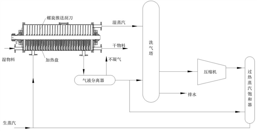
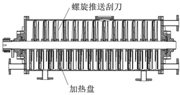
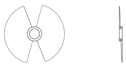
[0022] attached figure 1 It is a schematic diagram of a heat pump drying system disclosed in the present invention, which mainly includes a dryer and a heat pump system. The dryer used is a spiral push disc dryer, and the spiral push disc dryer includes a drying chamber cylinder, The central transmission shaft, the heating plate and the spiral push scraper, the heating plate is fixed on the drying chamber cylinder, has a hollow cavity, with reinforcing ribs inside, and forms a heating medium circulation flow channel at the same time, and the spiral push scraper is fixed on the central drive On the axis, the heating plate and the spiral pushing scraper are arranged alternately, the rotating surface of the spiral pushing scraper is parallel to the surface of the heating plate, and the rotating surface of the spiral pushing scraper sweeps the surface of the heating plate. The spiral pushing scraper adopts an opposing double helix structure, the helix angle is 5 degrees, and the c...

Embodiment 2

[0025] A heat pump drying method, using the spiral push disc dryer disclosed in the present invention to dry wet materials, the wet material enters the drying system continuously through the wet material inlet provided on the spiral push disc dryer, and the screw push scraper is used to dry the wet materials. Under the action of pushing, the wet material continuously moves to the dry material outlet. During the moving process, it is heated and dried by the heating plate. After the moisture content reaches the drying requirement, it is discharged from the dry material outlet to the drying system. Under the tumbling action of the spiral push scraper, the contact surface between the wet material and the heating plate is continuously updated and heated evenly, and the wet steam is discharged at the same time. In the initial stage of drying, raw steam is supplied to the cavity of the heating plate by the steam pipe, and the condensed water and non-condensable The steam enters the ga...


PUM


Abstract

The invention relates to a heat pump drying system and method. The system includes a spiral push disc dryer, a gas-liquid separator, a scrubber, a steam compressor, and a superheated steam saturator. The material is dried to produce wet steam. The wet steam goes through the scrubber to remove the solid dust contained in the steam, and then enters the steam compressor to increase the temperature and pressurize. The material is heated and dried in the heating plate cavity of the push plate dryer, and the condensed water and non-condensable steam are discharged into the gas-liquid separator for separation. The saturator supplies the water while recovering the waste heat it contains. The spiral push disc dryer used in this system can adjust the layout of the heating plate and the structure of the spiral push blades according to the characteristics of the material to be dried. The heat transfer area is large, the material stirring and transportation are uniform and stable, and the heat pump system is coupled at the same time to make the drying process more efficient and energy-saving. .

Description

technical field [0001] The invention belongs to the field of drying equipment, and in particular relates to a heat pump drying device. Background technique [0002] The drying process usually refers to the unit operation of using heat energy to vaporize the moisture contained in the material and reduce the moisture content of the product. It is widely used in various industries such as chemical industry, food, medicine, agriculture and forestry, and belongs to the unit operation of high energy consumption. With the increasing requirements of human society for environmental protection and the continuous increase of energy prices, how to improve drying efficiency and reduce process energy consumption has become the main research direction in the drying field. Heat pump technology refers to an energy-saving technology that upgrades low-grade heat energy to high-grade heat energy by consuming part of the reverse cycle net work. Therefore, combining heat pump technology with the...

Claims


Application Information

Patent Timeline
Patent Type & Authority Patents(China)
IPC IPC(8): F26B17/20F26B21/00F26B25/00F26B25/04F26B25/22
CPCF26B17/20F26B21/001F26B25/002F26B25/04F26B25/22Y02P70/10
Inventor 夏君君于会满尹海蛟全晓宇陈玉林刘莉谢源圩
Owner 天津乐科节能科技有限公司
Why Eureka
Try Eureka