Supercharge Your Innovation With Domain-Expert AI Agents!

Power amplification system and related power amplification method suitable for Bluetooth device

A technology for power amplification and Bluetooth device, which is applied to power amplifiers, components of amplification devices, and improvement of amplifiers to improve efficiency. , low cost effect

Pending Publication Date: 2020-10-27
REALTEK SEMICON CORP
View PDF5 Cites 0 Cited by
  • Summary
  • Abstract
  • Description
  • Claims
  • Application Information

AI Technical Summary

Problems solved by technology

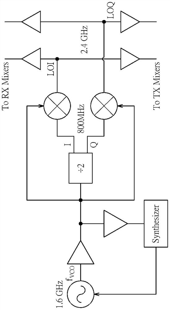
The disadvantage of this method is that in addition to the 2.4GHz signal at the output of the mixer, there will be an additional non-ideal spur (spur) at 800MHz, which will greatly affect the characteristics of power amplification.
However, the disadvantage of the above approach is that the non-ideal spike will get closer to the desired output frequency with the degree of decimalization
[0008] In addition, U.S. Patent No. US9548774 discloses an N-path filter architecture for generating a band-reject frequency response through the N-path filter, and the output uses double sideband (DSB) The mixer filters out the non-ideal spikes, but the disadvantage is that it needs to generate the clock pulses required for N-way filtering. If N=4, it needs to generate 25% duty cycle clock pulses. If there is good filtering The effect must increase the order
The disadvantage of the above method is that it is not easy to expand the order, and the higher the order, the smaller the duty cycle of operation, and therefore the more power consumption
[0009] In addition, U.S. Patent Nos. US7515931 and US8121214 propose to use a band-pass filter (BPF) to filter out non-ideal spikes. Although the band-pass filter is relatively simple, it has the disadvantage of occupying a large area, which is undoubtedly a cost increase
[0010] To sum up, many prior technologies cannot improve the pulling effect of power amplifiers without causing side effects, so there is a real need for a novel method and related circuits to improve the above problems

Method used


Image

  • Power amplification system and related power amplification method suitable for Bluetooth device
  • Power amplification system and related power amplification method suitable for Bluetooth device
  • Power amplification system and related power amplification method suitable for Bluetooth device

Examples


Embodiment Construction

[0039] Certain terms are used in the specification and subsequent claims to refer to particular elements. It should be understood by those skilled in the art that hardware manufacturers may use different terms to refer to the same element. This description and subsequent patent applications do not use the difference in name as a way to distinguish components, but use the difference in function of components as a criterion for distinguishing. The "comprising" mentioned throughout the specification and subsequent claims is an open term, so it should be interpreted as "including but not limited to". In addition, the term "coupled" herein includes any direct and indirect electrical connection means. Therefore, if it is described in the text that a first device is coupled to a second device, it means that the first device may be directly electrically connected to the second device, or indirectly electrically connected to the second device through other devices or connection means....


PUM


Abstract

The invention provides a power amplification system which comprises a voltage-controlled oscillator, a frequency eliminator, a frequency mixer and an addition amplifier. The voltage-controlled oscillator is used for providing an input signal of which the frequency is non-integer multiples of a preset frequency; the frequency eliminator is coupled to the voltage-controlled oscillator and is used for receiving the input signal and eliminating the frequency of the input signal so as to respectively generate an in-phase signal and a quadrature signal corresponding to the input signal; the frequency mixer is coupled to the voltage-controlled oscillator and the frequency eliminator and is used for mixing the input signal transmitted by the voltage-controlled oscillator and the in-phase signal transmitted by the frequency eliminator so as to output a mixed signal; the addition amplifier is coupled to the mixer and the frequency eliminator, and is used for integrating the mixed signal and theorthogonal signal to generate an output signal with a predetermined frequency.

Description

technical field [0001] The invention relates to the application of the power amplifier, especially to the power adjustment of the Bluetooth (Bluetooth) transmission. Background technique [0002] For a traditional direct-up transmitter, if the frequency of the voltage controlled oscillator (VCO) is chosen to be at the same frequency as the even harmonic of the power amplifier (PA), In general, the frequency of the VCO may be affected by the frequency of the power amplifier, also known as the power amplifier pulling effect (PA-pulling), which makes the error vector magnitude (Error Vector Magnitude, EVM) worse, thereby deteriorating the communication quality. Taking a 2.4GHz Bluetooth transmitter as an example, when the VCO signal is 2.4GHz or its multiples (such as 4.8GHz, 9.6GHz), the above power amplifier pulling effect will occur. [0003] At present, some previous technologies have been set out to solve the above problems. In order to have a more specific concept, the f...

Claims


Application Information

Patent Timeline
Patent Type & Authority Applications(China)
IPC IPC(8): H03F1/02H03F3/21H03F3/24H03L7/093H03L7/099H03D7/16H04B1/04
CPCH03F1/0205H03F3/21H03F3/245H03L7/093H03L7/099H03D7/16H04B1/0475H04B2001/0441
Inventor 邓平援
Owner REALTEK SEMICON CORP
Features
  • R&D
  • Intellectual Property
  • Life Sciences
  • Materials
  • Tech Scout
  • Unparalleled Data Quality
  • Higher Quality Content
  • 60% Fewer Hallucinations
Learn More