Supercharge Your Innovation With Domain-Expert AI Agents!

Magnetoelectric switch circuit

A magnetoelectric switch and circuit technology, applied in electronic switches, electrical components, pulse technology, etc., can solve problems such as difficulty in product replacement

Pending Publication Date: 2020-10-27
佛山市顺德区博为电器有限公司
View PDF0 Cites 0 Cited by
  • Summary
  • Abstract
  • Description
  • Claims
  • Application Information

AI Technical Summary

Problems solved by technology

However, the number of threads required by the two is different, and it is difficult to replace the products that have been finalized

Method used


Image

  • Magnetoelectric switch circuit
  • Magnetoelectric switch circuit

Examples


Embodiment Construction

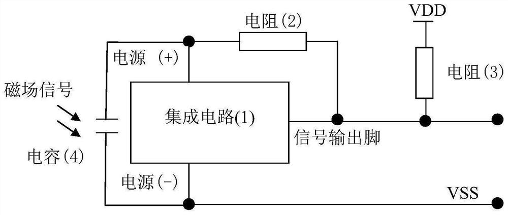
[0007] Attached below figure 1 Examples illustrate the present invention.

[0008] figure 1 In the embodiment, the integrated circuit (1) is a sensor, one end of the resistor (2) is connected to the signal output pin of the integrated circuit (1), and the other end is connected to the power supply (+). An integrated circuit (1), a resistor (2) and a capacitor (4) are used as a detection unit and placed at a position where a magnetic field is to be induced. The resistor (3) is placed in the user control system and connected to VDD of the system DC power supply. In this way, the detection unit and the user control system only need two wires, the signal output pin and VSS, to connect.

[0009] When the magnetic field is not detected, the current of the signal output pin is low, and the voltage drop on the resistor (3) is small, so the signal output pin is at a high level; when a magnetic field is detected, the current of the signal output pin is large, and the voltage drop on ...


PUM


Abstract

The invention relates to a magnetoelectric switching circuit, which comprises an integrated circuit (1), a resistor (2), a resistor (3) and a capacitor (4), and is characterized in that the integratedcircuit (1) is a Hall element. The circuit has the advantages of high reliability of a semiconductor circuit and the wiring of two wires of the reed switch, and a reed switch can be directly replacedas long as the proper resistor (3) is selected.

Description

technical field [0001] The present invention is a circuit involving a magnetic field inductive switch. Background technique [0002] The semiconductor magnetic field sensing element is mainly a Hall effect element, which requires three wires for power supply (+), power supply (-), and signal output. The design takes up space, and the cost increases significantly when the wire is long. [0003] The mechanical magnetic field sensing element is mainly a reed switch, which is packaged in glass, which is easy to break and fail during production and use. If it can be replaced by a 3-pin Hall element, the advantages of semiconductor products can be fully utilized: the plastic package is not easy to break , Non-contact switch action life is long. However, the number of threads required by the two is different, and it is difficult to replace the products that have been finalized. Contents of the invention [0004] Invented and designed a semiconductor magnetic field induction swi...

Claims


Application Information

Patent Timeline
Patent Type & Authority Applications(China)
IPC IPC(8): H03K17/90
CPCH03K17/90
Inventor 戴修敏
Owner 佛山市顺德区博为电器有限公司
Features
  • R&D
  • Intellectual Property
  • Life Sciences
  • Materials
  • Tech Scout
  • Unparalleled Data Quality
  • Higher Quality Content
  • 60% Fewer Hallucinations
Learn More