Blasting dust purification treatment equipment

A treatment equipment and dust purification technology, which is applied in the fields of dust removal, chemical instruments and methods, and separation of dispersed particles, etc., can solve the problems of limited effective dust absorption range and low reliability of use

Inactive Publication Date: 2020-10-30
惠安县崇武镇栓锋广告设计中心
View PDF3 Cites 4 Cited by
  • Summary
  • Abstract
  • Description
  • Claims
  • Application Information

AI Technical Summary

Problems solved by technology

[0004] The purpose of the present invention is to solve the problem that the existing engineering blasting dust degradation treatment device has a limited range of effective absorption of dust, resulting in low reliability, and proposes a blasting dust purification treatment equipment

Method used


Image

  • Blasting dust purification treatment equipment
  • Blasting dust purification treatment equipment
  • Blasting dust purification treatment equipment

Examples


Embodiment 1

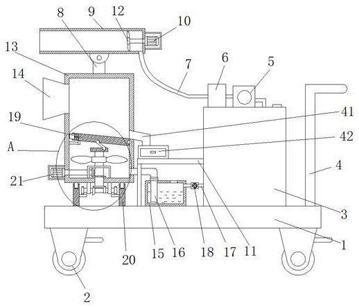
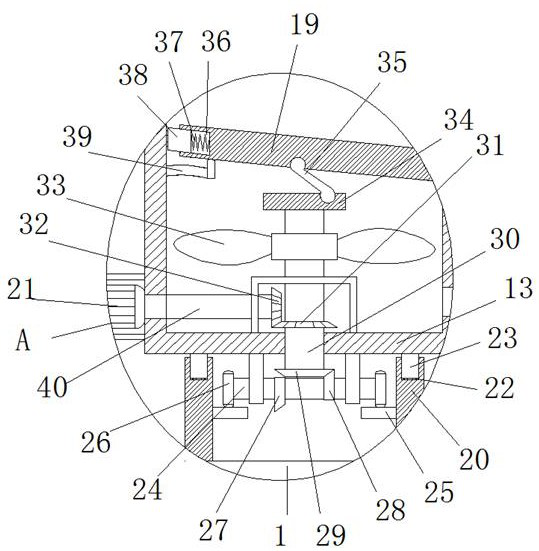
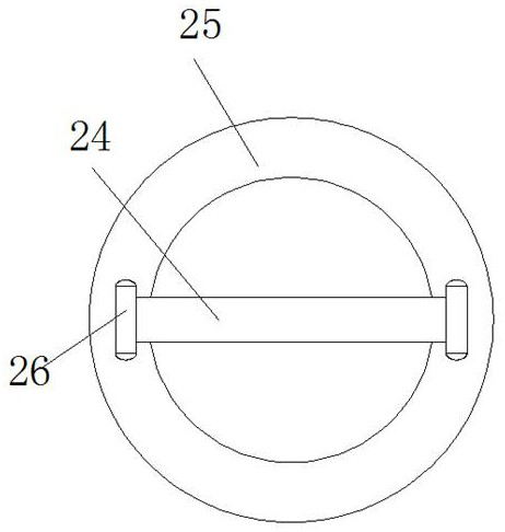
[0030] refer to Figure 1-5 , a blasting dust purification treatment equipment, comprising a base plate 1, four universal wheels 2 are arranged on the bottom of the base plate 1, brake pads are arranged on the four universal wheels 2, and the top of the base plate 1 is fixedly connected with an annular block 20, The liquid tank 15, the water tank 3 and two push handles 4, the top of the annular block 20 is rotated and installed with a rectangular box 13, and one side of the rectangular box 13 is connected with a dust suction port 14, the dust suction port 14 is a horn structure, and the rectangular box 13 The top of the support rod 8 is fixedly installed, and the top of the support rod 8 is rotated and installed with an atomizing cylinder 9, which is connected with an air blowing structure. The top of the water tank 3 is connected with a water pump 5, and the water outlet of the water pump 5 is connected with a fog The atomizer 6, the same hose 7 is connected between the atomi...

Embodiment 2

[0041] refer to Figure 1-5 , a blasting dust purification treatment equipment, comprising a base plate 1, four universal wheels 2 are arranged on the bottom of the base plate 1, brake pads are arranged on the four universal wheels 2, the brake pads can be fixed to the universal wheels 2, the base plate The top of 1 is fixedly connected with an annular block 20, a liquid tank 15, a water tank 3 and two push handles 4 by screws, and the top of the annular block 20 is rotated to install a rectangular box 13, and one side of the rectangular box 13 is connected with a dust suction port 14, The dust suction port 14 is a trumpet structure, the top of the rectangular box 13 is fixedly installed with a support rod 8 by welding, and the top of the support rod 8 is rotatably installed with an atomizing tube 9, and the atomizing tube 9 and the support rod 8 are connected by screw rotation, which can be adjusted The inclination angle of the atomizing cylinder 9, the atomizing cylinder 9 i...


PUM


Abstract

The invention belongs to the technical field of dust treatment and especially relates to blasting dust purification treatment equipment. The invention aims to overcome the problem that an existing engineering blasting dust degradation treatment device is limited in effective dust absorption range and is thus low in use reliability. The blasting dust purification treatment equipment comprises a bottom plate, wherein four universal wheels are arranged at the bottom of the bottom plate; brake pads are arranged on the four universal wheels; an annular block, a liquid tank, a water tank and two push handles are fixedly connected to the top of the bottom plate; a rectangular box is rotationally installed at the top of the annular block; one side of the rectangular box communicates with a dust suction port; the dust suction port is of a horn structure; a supporting rod is fixedly installed at the top of the rectangular box; an atomizing cylinder is rotationally installed at the top of the supporting rod; the atomizing cylinder is connected with an air blowing structure; the top of the water tank communicates with a water pump; and a water outlet of the water pump communicates with an atomizer. The blasting dust purification treatment equipment is simple in structure and convenient to operate, a dust collection and dust suppression range can be expanded, and use performance is improved.

Description

technical field [0001] The invention relates to the technical field of dust treatment, in particular to blasting dust purification treatment equipment. Background technique [0002] The engineering blasting dust degradation treatment device is an auxiliary device used to treat the dust generated during the engineering blasting process and avoid dust pollution to the construction site. It has been widely used in the fields of engineering construction and environmental protection. [0003] The existing engineering blasting dust degradation treatment device has a limited range of effective dust absorption, resulting in low reliability in use. Contents of the invention [0004] The purpose of the present invention is to solve the problem that the existing engineering blasting dust degradation treatment device has a limited range of effective dust absorption, resulting in low reliability, and proposes a blasting dust purification treatment device. [0005] In order to achieve ...

Claims


Application Information

Patent Timeline
Patent Type & Authority Applications(China)
IPC IPC(8): B01D50/00B08B15/00
CPCB08B15/007B01D50/60
Inventor 潘建锋林素妹
Owner 惠安县崇武镇栓锋广告设计中心
Why Eureka
Try Eureka