Continuous and efficient soil remediation device

A soil remediation and high-efficiency technology, applied in the field of soil remediation, can solve the problems of limited soil remediation effect, waste, volatile chemicals, etc., achieve good repair effect, reduce waste, and ensure efficiency

Inactive Publication Date: 2020-10-30
陈文华
View PDF1 Cites 6 Cited by
  • Summary
  • Abstract
  • Description
  • Claims
  • Application Information

AI Technical Summary

Problems solved by technology

[0004] The entire device is moved by pushing the push frame to drive the universal wheel, and the power of the second motor is used to drive the excavation wheel to move by the first pulley and the second pulley, so as to overturn and crush the soil and spray it on the soil through the shower head Repairing in the center facilitates the operation of the staff and greatly enhances the practicability of the whole device. Although the device can repair the soil, since its repair materials are sprayed on the surface of the soil, the repair effect on the deep soil Limited, and the medicine is easy to volatilize, causing waste

Method used


Image

  • Continuous and efficient soil remediation device
  • Continuous and efficient soil remediation device
  • Continuous and efficient soil remediation device

Examples


Embodiment 1

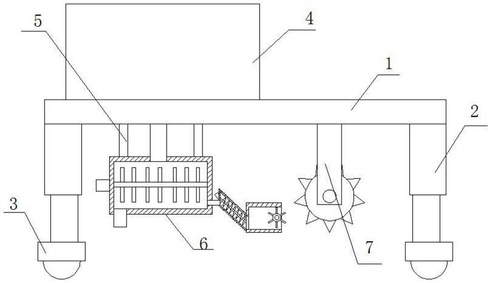
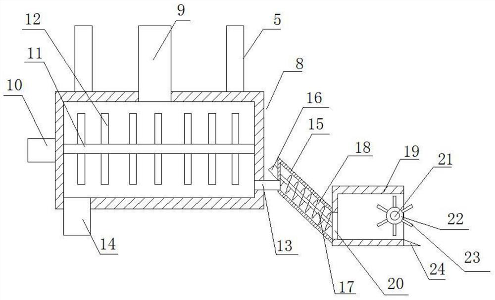
[0024] see Figure 1-5 , in an embodiment of the present invention, a continuous and efficient soil remediation device includes a frame 1, electric telescopic legs 2 are arranged at the four corners of the lower end of the frame 1, and universal wheels 3 are installed at the lower ends of the electric telescopic legs 2 The upper side of the frame 1 is provided with a repair agent box 4, the lower left part of the frame 1 is connected with a repair mechanism 6 through a connecting rod 5, and the lower right part of the frame 1 is provided with a soil-turning mechanism 7, the The repair mechanism 6 includes a repair box 8, the upper end of the repair box 8 is connected with the repair agent box 4 through the liquid inlet pipe 9, the upper end of the repair box 8 is connected with the frame 1 through the connecting rod 5, and a stirring mechanism is arranged in the repair box 8 , the right end of the repair box 8 is provided with a soil feeding pipe 13, the lower left end of the ...

Embodiment 2

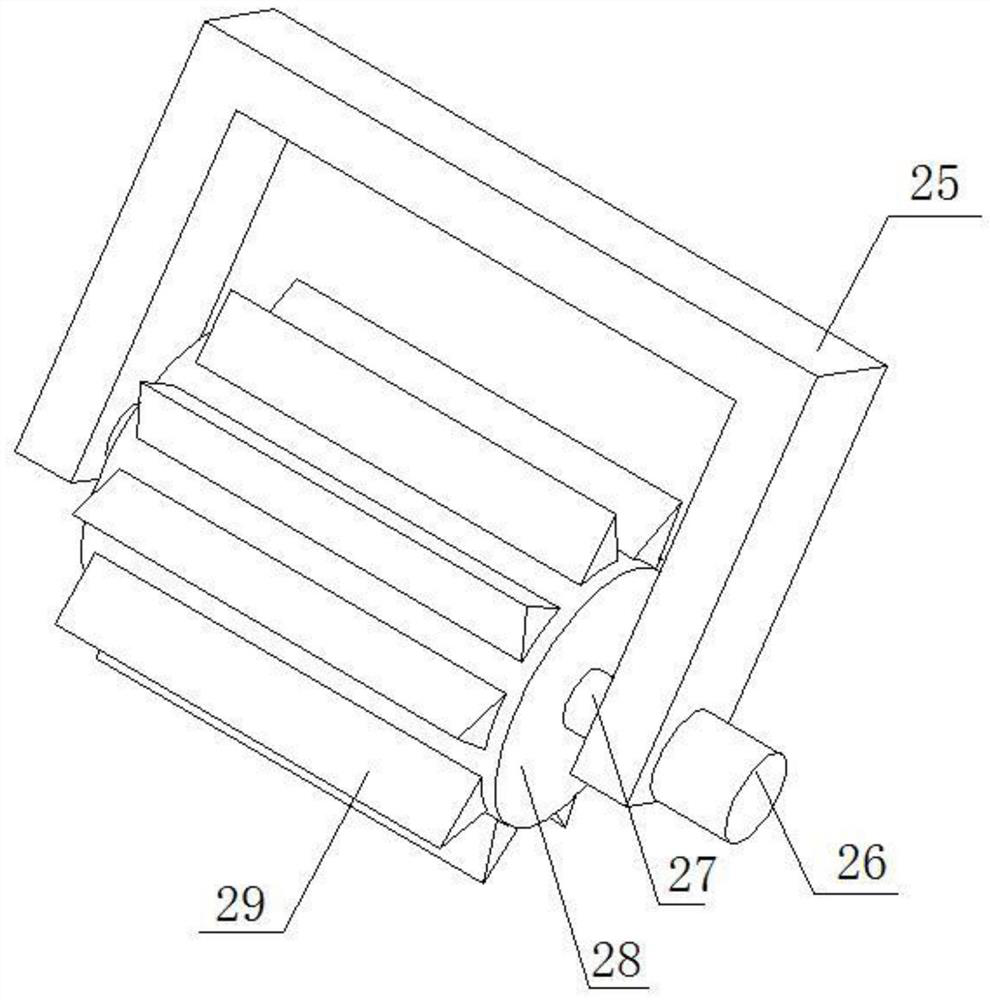
[0030]On the basis of Embodiment 1, the soil turning mechanism includes a bracket 25, a third motor 26 is installed on the outside of the lower end of the bracket 25, and the output end of the third motor 26 is provided with a rotating shaft 27 that is rotatably connected to the bracket 25 , the outer side of the rotating shaft 27 is provided with a rotating cylinder 28, and the outer side of the rotating cylinder 28 is provided with a plurality of tilling knives 29. The structural arrangement of the device drives the rotary cylinder to rotate through the third motor, so that the soil is turned by the tiller.


PUM


Abstract

The invention relates to the field of soil remediation, in particular to a continuous and efficient soil remediation device. The device includes a rack, electric telescopic legs are arranged at the four corners of the lower end of the rack, universal wheels are mounted at the lower ends of the electric telescopic legs, a remediation agent box is arranged on the upper side of the rack, the left portion of the lower end of the rack is connected with a remediation mechanism through a connecting rod, a soil turning mechanism is arranged at the right part of the lower side of the rack, the remediation mechanism comprises a remediation box, the upper end of the remediation box is connected with the remediation agent box through a liquid inlet pipe, the upper end of the remediation box is connected with the rack through a connecting rod, a stirring mechanism is arranged in the remediation box, a soil inlet pipe is arranged at the right end of the remediation box, a soil outlet is formed in the left end of the lower side of the remediation box, the remediation box is connected with a soil conveying mechanism through the soil inlet pipe, and the right end of the soil conveying mechanism isconnected with a soil shoveling mechanism. Due to the arrangement of the structure, soil on the lower portion can also have a good remediation effect, waste of liquid medicine can be reduced to a certain extent, and practicability is high.

Description

technical field [0001] The invention relates to the field of soil restoration, in particular to a continuous and efficient soil restoration device. Background technique [0002] Soil remediation is a technical measure to restore the normal function of polluted soil. In the soil remediation industry, there are more than one hundred existing soil remediation technologies, and there are more than ten commonly used technologies, which can be roughly divided into three methods: physical, chemical and biological, or refer to the transfer and absorption of physical, chemical and biological methods. , degrade and transform the pollutants in the soil, reduce its concentration to an acceptable level, or convert toxic and harmful pollutants into harmless substances. Since the 1980s, many countries in the world, especially developed countries, have formulated and Contaminated soil remediation and remediation programs have been launched, thus forming a new soil remediation industry. ...

Claims


Application Information

Patent Timeline
Patent Type & Authority Applications(China)
IPC IPC(8): B09C1/00A01B77/00
CPCA01B77/00B09C1/00
Inventor 陈文华
Owner 陈文华
Why Eureka
Try Eureka